


11 — ENG
D20498 Rev. 0 6/9/00
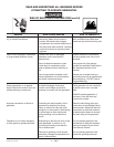
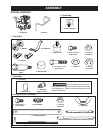
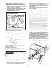
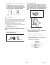
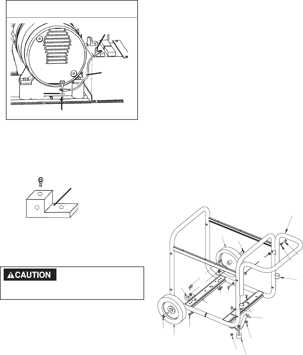
INSTALLING WHEEL KIT
The Craftsman Wheel Kit was designed to greatly
improve the portability of your generator.
1
2
8
8
10
5
11
9
7
11
12
8
6
2
1
4
E
n
g
i
n
e
S
u
p
p
o
r
t
9
3
8
8
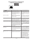
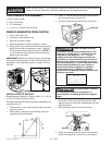
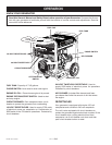
GROUNDING THE GENERATOR
A grounding lug is supplied with the generator for use
when required by local electrical ordinances. Refer to
article 250 of the National Electrical Code to clarify
any needed grounding information. Your local electric
company or a certified electrician should be able to
help you with this information.
NOTE: Your engine is already grounded to the frame
by a grounding strap.
NOTE: Always follow state regulations for proper oil
disposal.
• Place generator on level ground; drain all gas and
oil from the engine (see engine manual for correct
procedure).
• Place a 1” thick x 1’ square piece of wood on the
ground in front of the engine. With the help of
Drain gas and oil before
assembling the portability
kit. Failure to do so will cause damage to the
engine.
another person, tilt the generator and rest the
recoil starter on the wood. NOTE: This will support
the gasoline engine during assembly and make
assembly easier.
• Place a handle cap (7) onto each end of handle
prior to installation.
• The handle should be installed on the electrical
outlet end of the generator. Place one washer (12)
on long cap screws (11). Align the handle brack-
ets with the upper holes pre-drilled in the genera-
tor frame. Place mentioned screws through frame
and handle brackets. Secure with lock nuts
(8) and tighten.
• Locate the engine support. Place one wheel
bracket (4) on top of support as shown in illustra-
tion. Align with the pre-drilled holes in support.
Place 2 cap screws (9) through holes in bracket
and support. Secure with 2 lock nuts (8) and
tighten.
• Insert one shoulder bolt (2) into wheel (1). Insert
threaded end of bolt through wheel bracket,
secure with lock nut (3) and tighten. NOTE: The
wheel will not rub frame if installed properly.
• Repeat the above steps for the opposite side.
• Insert the threaded stud of rubber foot (10)
through the middle hole of the foot bracket (5).
Secure with lock nut (8) and tighten.
• Locate the support under the electrical outlet end
of the generator. Position foot bracket (5), with
rubber foot installed, under the support and align
the holes in the foot bracket (5) with the slots in
the support. Place one cap screw (9) through each
slot in the support and the holes in the foot
bracket. Secure with the lock nuts (8) and tighten.
• Once completed, the wheel kit is ready for use.
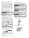
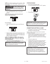
Grounding Lug
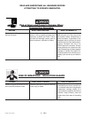
Negative
(-) Battery
Cable
(-) Negative Battery
Cable Connection
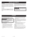
(-) Negative Battery Cable Connection
Star
Washer
NOTE: Make sure red battery boots cover
positive battery cable terminals at battery and
solenoid
• Attach one end of the negative (black) cable to the
negative (-) terminal on the battery.
• Attach the other end of the negative (black) cable
to the frame as shown. Install the star washer
between the cable and the frame.
IMPORTANT: See Caution on page 10
before assembling battery.