8
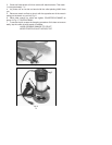
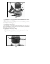
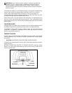
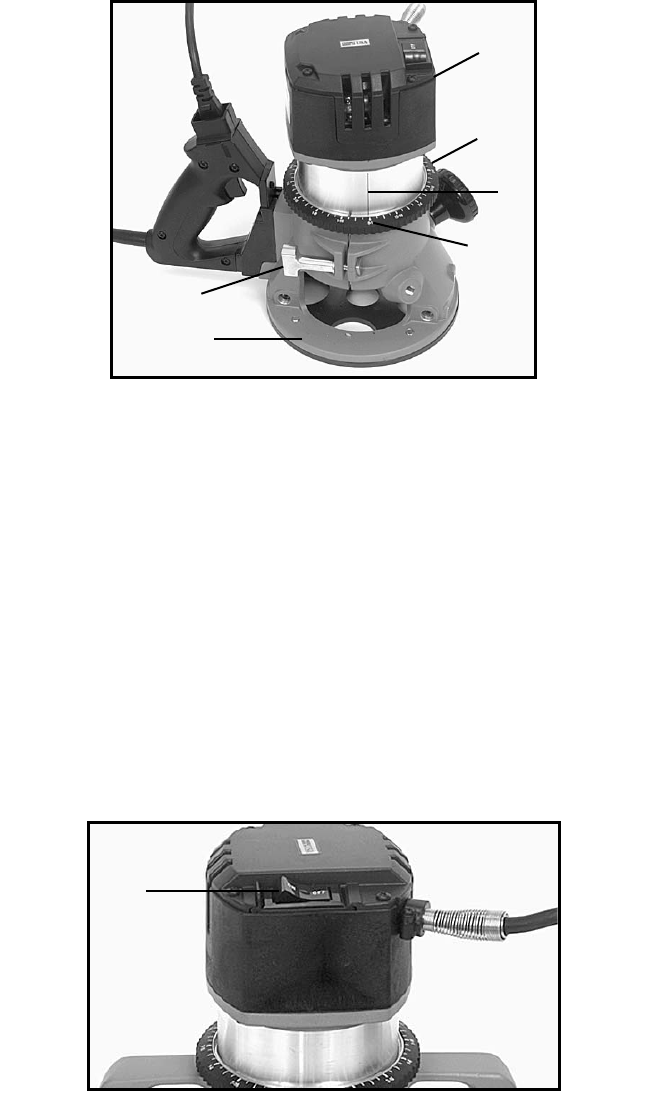
5. Turn motor unit (F) Fig. 5 CLOCKWISE until bit touches the wood surface.
6. Tighten clamp screw (A) Fig. 5.
7. Rotate depth adjusting ring (B) Fig. 5 until the zero-line (C) is opposite the
index line (D) on the housing.
8. Loosen clamp screw (A) Fig. 5.
9. Tip the router so bit is clear of the wood surface. Turn motor unit (F)
Fig. 5, CLOCKWISE until the index line (D) on the motor housing reaches the
desired depth indicated on the ring.
10. Tighten clamp screw (A) Fig. 5 firmly.
NOTE: Setting the index line to
1
/
4" on the ring means the cutting
edge of the bit is exposed
1
/
4" below the base.
Fig. 5
F
B
D
C
E
A
A
Fig. 6


