


P/N 471048 Rev. G 1-22-04
18
INDOOR INSTALLATION (USA ONLY)
OUTDOOR SHELTER INSTALLATION (CANADA)
(See additional instructions for outdoor
PowerMax units in PowerMax Appendix)
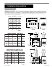
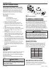
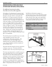
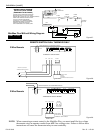
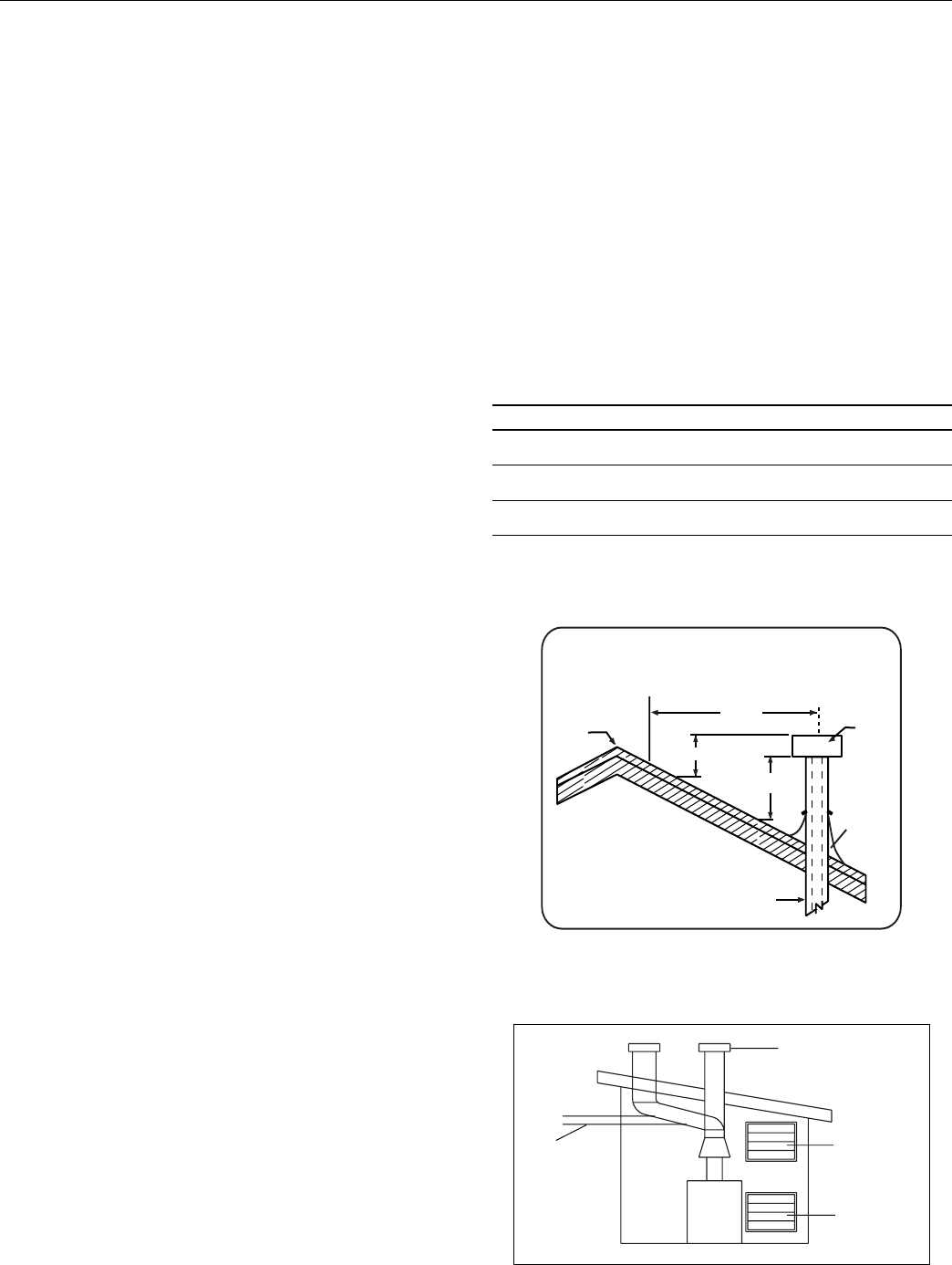
All products of combustion and vent gases must
be completely removed to the outside atmosphere
through a vent pipe which is connected to the
draft hood. A vent pipe extension of the same
size must be connected to the draft hood and
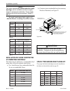
extended at least 2 feet higher than highest point
of the roof within a 10 foot horizontal radius, and
at least 3 ft. higher than the point at which it
passes through the roof, or as permitted by local
code; see Figures 21 and 22. The vent should
terminate with an approved vent cap (weather
cap) for protection against rain or blockage by
snow. Double-wall vent pipe and an approved
roof jack shall be employed through the roof
penetration. The use of double-walled type B vent
pipe is recommended.
The draft hood must be installed so as to be in the
same atmospheric pressure zone as the
combustion air inlet to the pool heater. The
certified (factory) draft hood
must not be
modified in any way and must be employed in
every indoor installation (with the exception of
the PowerMax units).
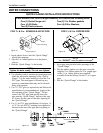
The heater must be located as close as practical to
a chimney or gas vent. The heater should be
installed at least 5 feet away from the pool or spa.
The heater must be placed in a suitable room on a
non-combustible floor or on a non-combustible
base and in an area where leakage from heat
exchanger or water connections will not result in
damage to the area adjacent to the heater or the
structure. When such locations cannot be
avoided, it is recommended that a suitable drain
pan with adequate drainage, be installed under the
heater. The pan must not restrict air flow.
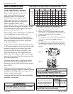
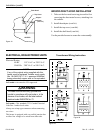
Installations in basements, garages, or
underground structures where flammable liquids
may be stored must have the heater elevated 18
inches from the floor using a non-combustible
base. The following minimum clearances from
combustible materials must be provided.
Side Front Back Top
Water Connection 18 in. 24 in.
Remaining 6 in. 6 in.
Ceiling Clearance 36 in.*
*To ceiling or roof.
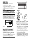
Installation (contd.)
Figure 22.
Vent terminated at
least 24 in. above
any object within 10 ft.
Vent
Cap
Ridge
Chimney
3 ft. min.
2 ft. min.
10 ft.
Roof
Jack
Figure 21.
* Rise
Air Supply
Gas Combustion
Air Supply
Ventilation
Vent Cap and
Riser Furnished
by Installer
* 1” Rise Per Foot
Recommended