


P/N 471048 Rev. G 1-22-04
16
16
Installation (contd.)
GAS CONNECTIONS
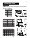
GAS LINE INSTALLATIONS
Before installing the gas line, be sure to
check which gas the heater has been
designed to burn. This is important
because different types of gas require
different gas pipe sizes. The rating plate
on the heater will indicate which gas the
heater is designed to burn. Table 7,
shows which size pipe is required for the
distance from the gas meter to the heater. The table
is for natural gas at a specific gravity of .65 and
propane at specific gravity of 1.5.
When sizing gas lines, calculate three (3) additional
feet of straight pipe for every elbow used.
When installing the gas line, avoid getting dirt,
grease or other foreign material in the pipe as this
may cause damage to the gas valve, which may
result in heater failure.
The gas meter should be checked to make sure that
it will supply enough gas to the heater and any other
appliances that may be used on the same meter.
The gas line from the meter will usually be of a
larger size than the gas valve supplied with the
heater. Therefore a reduction of the connecting gas
pipe will be necessary. Make this reduction as close
to the heater as possible.
The heater and any other gas appliances must be
disconnected from the gas supply piping system
during any pressure testing on that system, (greater
that ½ PSIG).
The heater and its gas connection must be leak
tested before placing the heater in operation. Do not
use flame to test the gas line. Use soapy water or
another nonflammable method.
A manual main shut-off valve must be installed
externally to the heater.
WARNING
Do not install the gas line union inside the heater
cabinet. This will void your warranty.
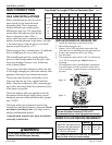
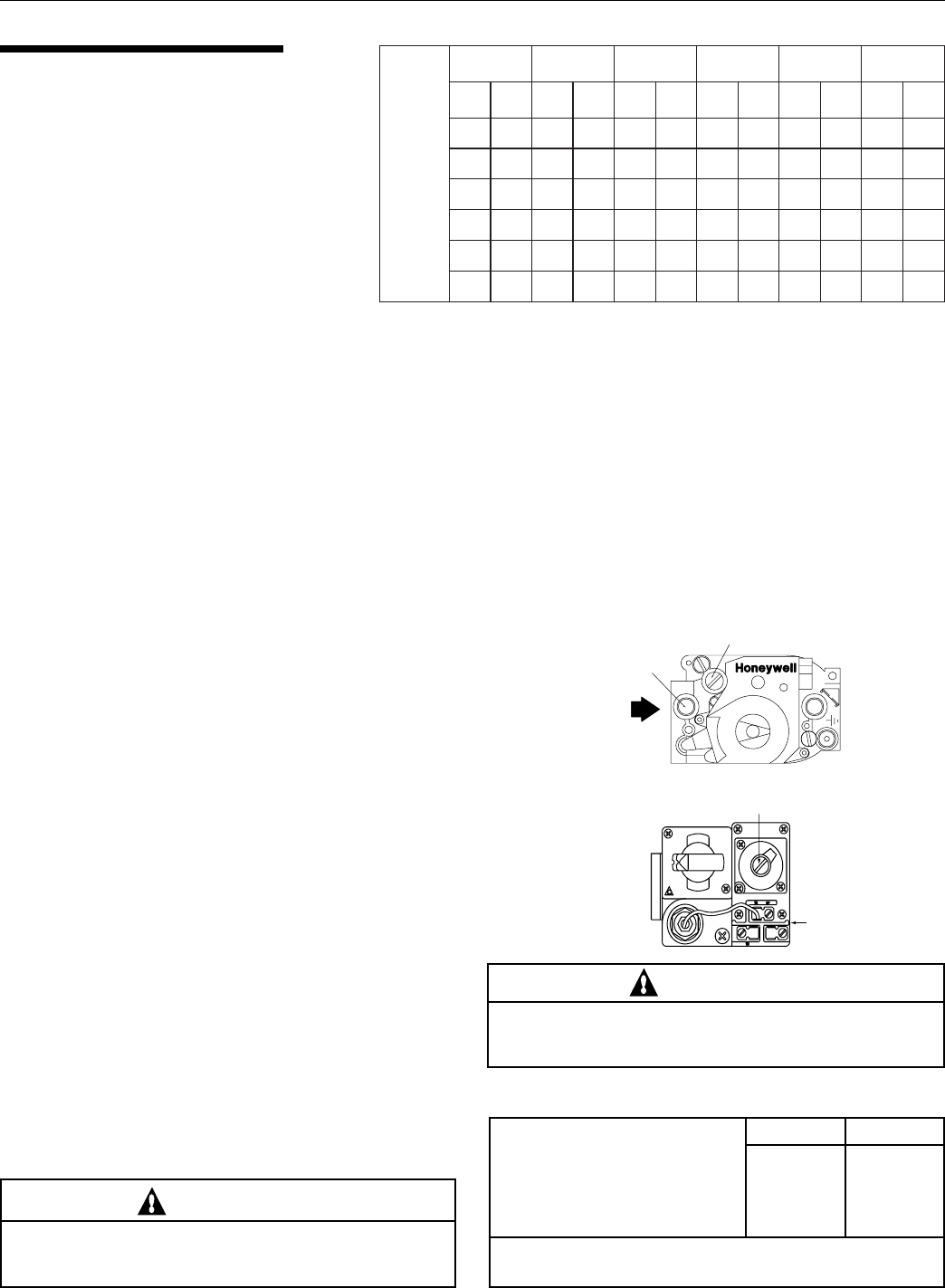
Pipe Sized For Length Of Run In Equivalent Feet
Table 8.
ledoM
051
002/591
052
003
053
004
.ni2/1.ni4/3.ni1.ni¼1.ni½1.ni2
taNPLtaNPLtaNPLtaNPLtaNPLtaNPL
'01'04'05'051'051'006 ------
-'02'03'08'521'052'054'006 ----
-'01'02'05'07'051'052'005'006 ---
-- '01'03'05'001'002'053'004'006--
-- '01'02'03'07'521'052'052'005'005-
--- '01'02'06'001'051'002'054'004-
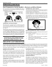
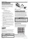
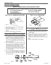
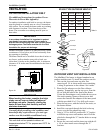
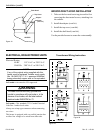
REGULATED MANIFOLD PRESSURE TEST
1. Attach the manometer to the heater jacket.
2. Shut off the main gas valve.
3. Remove 1/8 in. NPT plug on the outlet side of the
valve and screw in the fitting from the manometer kit.
4. Connect the manometer hose to the fitting.
5. Fire the heater.
6. The manometer must read 4 in. WC for natural gas,
11 in. WC for propane gas, while the heater is
operating.
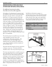
7. For adjustment, remove the Regulator Adjustment
Cap and using a screwdriver turn the screw clock-
wise to increase - counterclockwise to decrease gas
pressure.
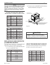
Table 7.
Natural
Propane
Maximum inlet gas pressure 10 in. WC 14 in. WC
Minimum inlet gas pressure **5 in. WC 12 in. WC
Normal manifold pressure 4 in. WC 11 in. WC
** 6 WC for 400 model
*All Readings are taken with the heater fired. Any adjustments
made with heater off will give incorrect readings.
HONEYWELL
PILOT
1/2 P.S.I.
PILOT
ADJ.
REGULATOR
ADJUSTMENT CAP
PRESS
TAP
OFF
ON
Regulator Adjustment Cap
1/8" NPT Plug
(Manifold Press)
1/8" NPT Plug
(Inlet Press)
Figure 16.
Figure 17.
CAUTION
The use of Flexible Connectors (FLEX) is NOT
recommended as they cause high gas pressure drops.
MINIMAX PLUS GAS PRESSURE REQUIREMENTS*