


MegaTherm Commercial Pool Heating Boiler
Page 7
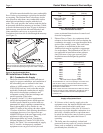
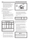
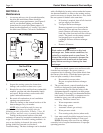
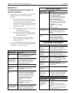
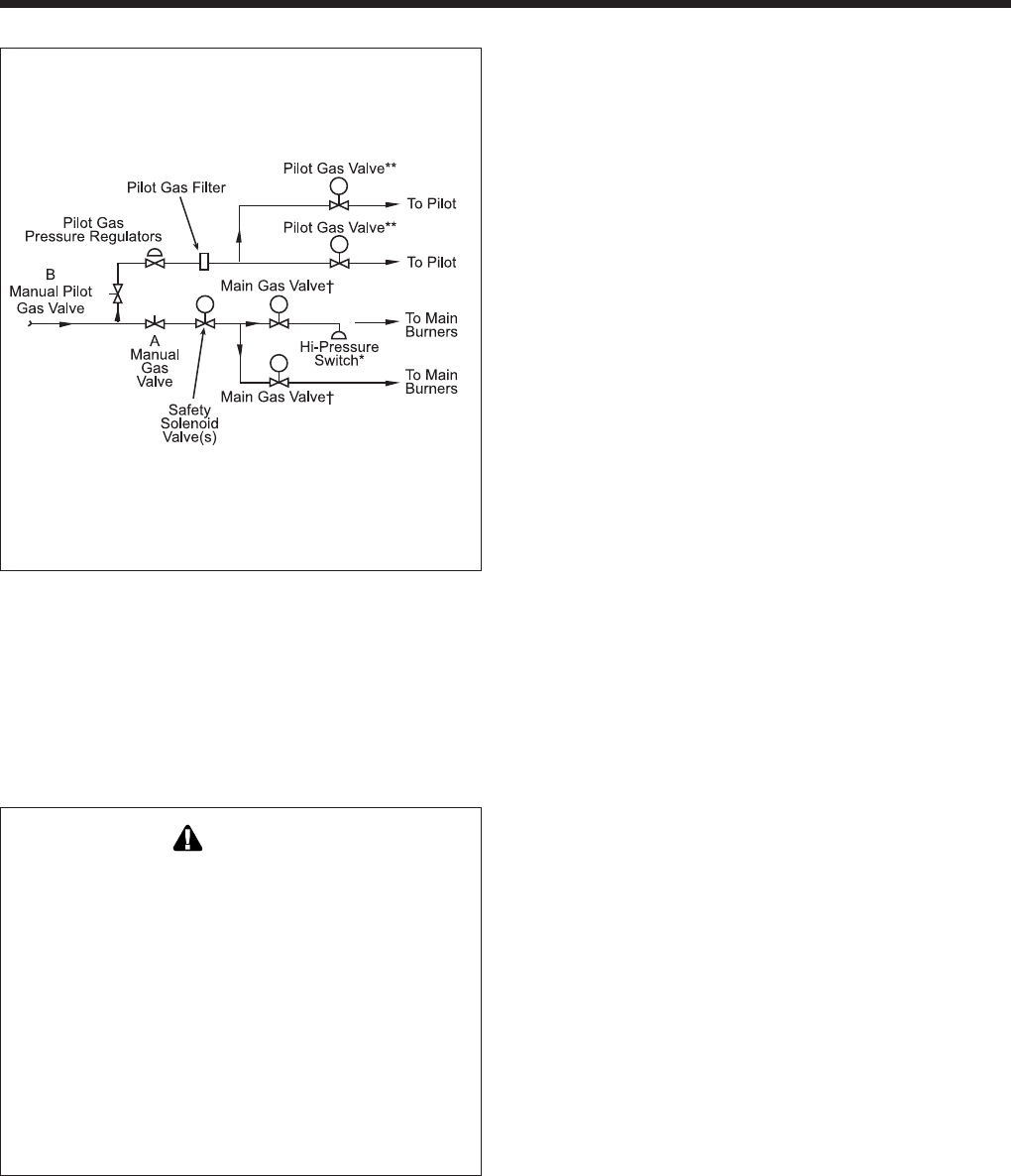
Arrangement of gas train components for on-off
firing are shown schematically in the Gas Piping
Diagram (see Figure 6).
2F. Electrical Wiring
WARNING
The boiler must be electrically grounded in
accordance with the most recent edition of the
National Electrical Code, ANSI/NFPA 70, and
in Canada, follow Canadian Electrical Code
CSA C22.1. Do not rely on the gas or water
piping to ground the metal parts of the boiler.
Frequently, plastic pipe or dielectric unions
isolate the boiler electrically. Service and
maintenance personnel who work on or around
the unit may be standing on wet floors and
could be electrocuted by a poorly grounded
boiler.
1. Check boiler wiring and pump for correct volt
age, frequency and phase. If the pump circuit is
other than 115V, check to see that the boiler is
provided with an appropriate transformer.
2. Wire the boiler and pump exactly as shown in
the wiring diagram supplied with the boiler.
3. The pump and boiler must be electrically
interlocked so the boiler cannot come on unless
the pump is running.
4. All field installed electrical safety devices and all
field installed devices (draft switches, relays,
timers, etc.) can be connected to the boiler
wiring at points shown in the wiring diagram
designated “Field Interlock.”
5. Auxiliary Time Clock Wiring. If a time clock is
used to control the filter pump operation, a
separate switch must be used to shut off the
boiler at least 15 minutes before the filter pump
is shut off. Wire the separate switch (sometimes
called a “Fireman Switch”) at the points shown
on the internal wiring diagram as “Field
Interlock.”
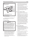
2G. Piping of System to Boiler
1. Be sure to provide gate valves at the inlet and
outlet to the boiler so it can be readily isolated
for service.
2. The pressure relief valve must be installed in the
tapped opening provided, or on a “Tee” fitting
when provided, in the boiler outlet header with
its outlet piped to a drain or floor sink. Special
attention must be given to relief valve settings in
installations where the boiler is located on the
ground floor of a tall building. The static
pressure of the system is elevated, and could
cause the relief valve to leak. Where no special
setting of the relief valve is ordered, the factory
will furnish a 75 psi setting. Never reduce the
relief valve opening. If necessary, install the
relief valve in a Tee immediately past the boiler
outlet. The weight of all water and gas piping
should be supported by suitable hangers or floor
stands. Check piping diagrams with local
applicable plumbing, heating and building
safety codes.
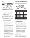
2H. General Water Piping
1. Plastic fittings, grids, or other elements of the
filter system are subject to damage by the
momentary “back syphoning” of hot water when
the pump stops. To prevent this backflow, install
a swinging gate check valve in the piping
between the filter and the boiler.
2. No Hartford Loop is required for anti-syphon
protection.
3. No water flow adjustments are required except
when a manual bypass valve is installed.
4. Do not install any valve or other variable
restriction in the return piping between the boiler
outlet and the pool.
5. The outlet pipe is carrying a large volume of
water which has bypassed the boiler combined
with a small volume of very hot water.
Note:
Main Gas Valves Incorporate
Gas Pressure Regulators
* Standard on sizes 3050-5000 (AGA models).
** Sizes 2000 & 2450 use one pilot gas valve.
† Sizes 2000, 2450 & 3050.
Figure 6. Gas Piping Diagram.