


MegaTherm Commercial Pool Heating Boiler
Page 5
2B-2. Venting
1. Model MT boilers have built-in draft diverters for
natural draft operation and must not be
connected into any portion of a mechanical draft
system under positive pressure. The flue outlet
must be connected to a clear, unobstructed vent
of adequate capacity terminating above the
highest point of the building with an approved
vent cap. The venting system should be installed
according to the latest edition of ANSI Z223.1
(or CAN1-B149) and any local codes having
jurisdiction.
IMPORTANT NOTE: Do not use sheet metal
screws at the snap lock joints of Type B gas vents.
2. Do not weld or fasten the vent pipe to the boiler
draft hood. The weight of the stack must not rest
on the boiler. The draft hood and top must be
easily removable for normal boiler service and
inspection.
3. Avoid long horizontal runs of the vent pipe, and
too many 90 degree elbows, reductions and
restrictions. Horizontal runs should have at least
a 1/4” rise per foot in the direction of flow. A
vent connector shall be supported for the design
and weight of the material employed to maintain
clearances and prevent physical damage and
separation of joints.
4. Avoid terminating boiler vents near air
conditioning or air supply fans. The fans can
pick up exhaust flue products from the boiler and
return them inside the building, creating a
possible health hazard. A minimum of 4 feet
horizontal distance must be maintained from
electric meters, gas meters, and relief equipment.
5. Always use double-wall or insulated vent pipe
(Type B or equivalent). In cold weather,
uninsulated outside vents can chill the rising flue
products, blocking the natural draft action of the
venting system. This can create a health hazard
by spilling flue products into the boiler room.
6. Avoid oversize vent piping or extremely long
runs of the pipe which may cause excessive
cooling and condensation. Rule of Thumb: The
total length of the vent, including the connector
and any offset, should not exceed 15 feet for
every inch of vent diameter. Longer total lengths
shown in venting tables are based on maximum
capacity, not condensation factors.
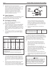
7. When the installation of a draft fan is necessary
in the venting system to which a Model MT
boiler is to be connected, the installation should
be engineered by competent personnel following
good engineering practices. The draft fan
supplier should be consulted for correct size. The
installation should be in accordance with the
latest edition of ANSI Z223.1 and any local
codes having jurisdiction. When a draft fan is
installed, a suitable draft switch must be used
and wired into the boiler control circuit at
terminal designated “Field Interlock,” to prevent
firing of the unit unless a positive draft has been
established (see Figure 3).
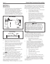
Figure 3. Draft Fan Wiring Diagram.
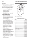
2C. Installation of Outdoor Units
1. Locate the boiler to provide the minimum
clearances as listed in Section 2A, “Boiler
Placement.”
2. Do not locate the boiler in an enclosure or wall
recess. Avoid locations where wind deflection
off structures might cause down draft. When
such wind conditions are possible, locate the unit
at least three (3) feet from the structures.
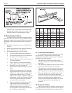
3. Never install the boiler under any kind of roof
overhang. Do not locate the unit below or
adjacent to any doors, windows, louvers, grills,
etc. which communicate in any way with an
inhabited area of a building. Even though such
communication might be through another
structure such as a garage or utility room (see
Figure 4).
Figure 4. Incorrect Outdoor Installation.