P/N 471048 Rev. G 1-22-04
8
Knob Stopper
Screw A
OPERATING (CONTROLS)
Dual Temperature Control System - (Electronic and Millivolt Models)
Operation (contd.)
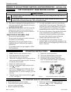
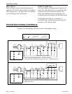
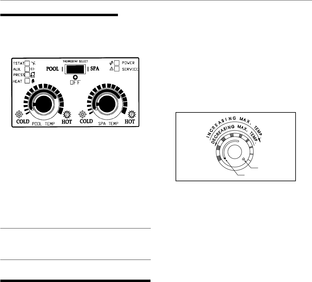
For convenience and economy all MiniMax Plus heaters
are equipped with two thermostats on the front of the heater
control panel; see Figure 7.
Figure 7.
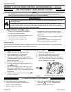
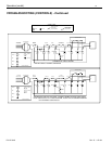
Figure 8.
THERMOSTAT KNOB STOPPER
Each thermostat is equipped with a mechanical stop that
can be locked or unlocked with use of a screwdriver to
prevent temperatures in excess of that desired by the user;
see Figure 8.
The maximum setting can be adjusted by loosening the screw
"A" and turning the stopper dial to desired maximum setting.
Lock the setting by tightening the screw. The Mechanical
stop is under the knob. Ensure that the knob is stopping at the
correct position when the knob is rotated clockwise from a
lower temperature position. (See Thermostat Adjustment.)
NOTE
To eliminate error due to piping heat losses,
measure pool temperature with an accurate
thermometer directly at the pool or spa.
THERMOSTAT ADJUSTMENT
The knob with locking feature eliminates the need for
constant thermostat adjustments. Set the knob pointer to
the desired pool or spa temperature.
If further adjustment is needed, rotate the knob until the
desired temperature is obtained. This knob position
corresponding to your desired maximum pool or spa
temperature may now be preset (locked) by the knob
stopper which prevents the knob from being turned beyond
the maximum temperature you set.
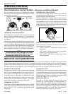
POWER (THERMOSTAT SELECT) SWITCH
The Pool/Off/Spa switch allows the heater to be turned off
when heating is not desired.
1. “Pool” position - Maintains selected pool
temperature.
2. “Off” position - Heater will not come on regardless
of drop in pool or spa temperature.
3. “Spa” position - This allows separate control of spa
water temperature.
INDICATOR LIGHT DESCRIPTION
The MiniMax Pool Heater provides nine status indicator lights, six can be seen from the front of the control panel which
help you understand the operation of the heater. If something should go wrong, the lights will aid in troubleshooting the
problem. Three additional lights can be seen after opening the control panel. These three lights give the service technician
advanced troubleshooting capability. All the LED lights are green with the exception of the red service LED.
POWER LIGHT (POWER)
The light is on at all times, in any switch position, indicating
24 VAC power is being supplied to the control circuit. If it
fails to light, no other light will be on. Possible causes are:
a) external power to the heater is disconnected, check
service panel circuit breaker or fuses; b) local circuit
breaker inside the transformer has tripped -- investigate
cause before resetting; c) transformer has failed.
THERMOSTAT (TSTAT)
This light is on when the thermostat contacts close, signaled
by the water temperature falling below the setpoint, calling
for the heater to fire to maintain the desired water
temperature.
AUXILIARY (AUX)
This light is on when it indicates the remote switch contacts
are closed. This allows you to observe if your remote switch
is properly closing the heater control circuit. When shipped
from the factory a jumper is installed to maintain closed
circuit in the absence of a remote switch.
PRESSURE (PRESS)
This light is on when Spa/Pool Selector switch is on,
indicates the circulation pump is running properly. If
pressure light fails to light, the pump may have lost its
prime or water flow may be restricted by an inadvertently
closed valve or clogged filter or pump basket. If you have
determined that there is no water flow restriction to the
heater, you should call a qualified serviceman.


