


mA.
If necessary, adjust R-24 to
obtain this value noting that counterclockwise rotation of its adjustment screw will cause an increase
in the span.
If either the span or offset trim are changed, it is suggested that both values be checked,
since there is some slight interaction between the two adjustments. Be sure to return the jumper to
the JW position at the conclusion of this adjustment procedure.
The Wind Speed channel should not normally require adjustment in the field.
4
mA
level. If necessary, adjust R-25 to obtain this value, noting that counterclockwise rotation of its
adjustment screw will cause the offset value to increase. Moving the jumper position to the “JF”
location will cause the loop current to its full scale value of 20
“JW”
position and
move it to the “JO” position.
This should force the wind direction loop current to its zero scale or 4
::: ““ .
The WMS-22 normally should not require adjustment of these controls. An exception occurs if for
any reason the wind sensor is changed or if the cabling to the wind sensor exceeds 200 feet in length.
In these cases the span control of the direction channel may require a slight adjustment.
A movable
jumper is included on the PC board direction channel to facilitate checking its offset and span
adjustments. To use this feature, remove the jumper normally in place at the
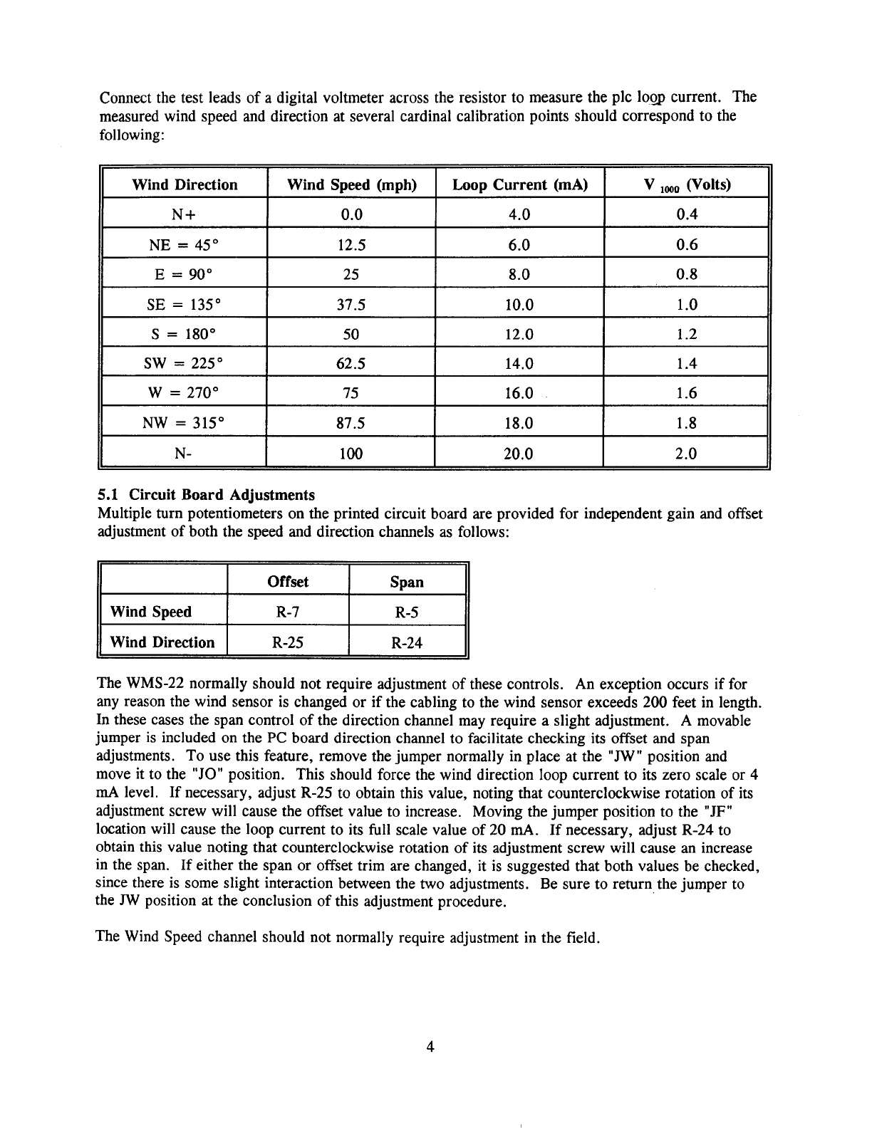
N -
I
100
I
20 . 0
I
2.0
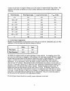
5.1 Circuit Board Adjustments
Multiple turn potentiometers on the printed circuit board are provided for independent gain and offset
adjustment of both the speed and direction channels
as follows:
II
I
1.4
W
=
270”
75 16.0
1.6
NW
=
315” 87.5 18.0
1.8
I
14.0
I
62.5
II
SW =
225”
1000
(Volts)
N+
0.0 4.0
0.4
NE = 45 ”
12.5
6.0
0.6
E = 90 ”
25
8.0
0.8
SE = 135 ”
37.5
10.0
1.0
S = 180 ”
50
12.0
1.2
(mA)
V
lo.9
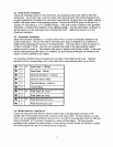
current.
The
measured wind speed and direction at several cardinal calibration points should correspond to the
following:
Wind Direction Wind Speed (mph) Loop Current
Connect the test leads of a digital voltmeter across the resistor to measure the plc