


mA.
4.0
INSTALLATION
4.1 Unpacking
Empty the loose packing material from the corrugated shipping container and carefully lift out the
wind sensor assembly.
List of Enclosed Materials
1.
Wind Speed, Wind Direction sensor, with 40 feet of cable
2.
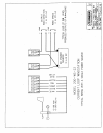
Transmitter Housing Assembly with I/O connection terminal strips input receptacle.
3.
Instruction Manual.
5-10”)
straddling the North direction (indicated by the set screw in the mounting base).
When the wind vane is pointing in this region, the loop current will be encoded as an underscale
value of approximately 3.6
mA)
output of the wind speed channel represents a measured 100 mph wind speed.
The full-scale span of the direction channel represents a full 360 degree swing of the wind vane.
The
potentiometer used as a direction sensor for wind direction has a small arc of resistance discontinuity
(typically
1”
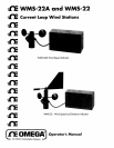
outside diameter pole. It is
supplied with 40 feet of cable for connection to the electronics housing.
The anemometer’s precision
ball bearing is protected from the weather and has lifetime lubrication.
The counterweight at the end
of the wind vane balances the weight of the moving mass over its supporting bearing.
It is important
that the wind sensor be installed in a location free from any obstructions that would distort the natural
flow of air across the sensor.
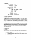
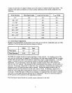
The full-scale (20
InA
Supply Voltage Range
10 to 48 Vdc
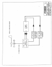
2-Wire Loop Interface Screw Terminal Block
3.0
GENERAL DESCRIPTION
3.1 Wind Speed Measurement
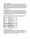
The WMS-22 wind sensor is designed to be mounted on the end of a
t o
20
ou t pu t
span
4
51
Mph
Current Loop
+5
Degrees
Threshold
f3%
F.S.
Wind Direction
Range O-360” Mechanical 350” Electrical
Resolution
2 Degrees
Accuracy
<l
mph
Measurement Accuracy
~
Averaging Interval
2.1 Seconds
Resolution
1 mph
Threshold
I
Measurement Range
O-100 mph
2.3 Specifications
Wind Speed