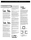
Switching Characteristic Graphs
Signal “on” with rising pressure
Setting SP* > RP**
Explanation:
When the switching point (SP) is adjusted HIGHER than the reset point (RP), then the switching output will be “normally off”.
When the switching point (SP) is adjusted LOWER than the reset point (RP), then the switching output will be “normally on”.
p
SP
RP
t
t
U
Signal “on” with falling pressure
Setting SP < RP
Signal “off” with rising pressure
Setting RP > SP
p
RP
SP
t
t
U
p
RP
SP
U
A
t
t
Signal “off” with falling pressure
Setting RP < SP
p
SP
RP
U
A
t
t
* SP = Switching point
**RP = Reset point
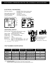
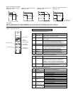
Pressure display
Switching
function graph
Switching output LED
Raise switching
or reset point button
Lower switching
or reset point button
Reset point button
Switching point button
Position of operating elements
Cod Meaning Requested code or code programming
CLC Clear code Deletion of current code
txx Delay time Setting of filter time constant
(Buffering time) xx = Switching output delay
xx {03, 06, 12, 24, 50} in ms and
xx {O.1, 0.2, O.4} in s.
OFS Offset Request for offset adjustment using ▼ and ▲ buttons
SC.H Short-circuit high Short-circuit monitoring activated
U. LO Voltage low Voltage monitoring activated
OFF Off Short-circuit or voltage monitoring deactivated
Std Standard mode Standard mode activated
HYS Hysteresis mode Hysteresis mode activated
FEn Window mode Window mode activated
U-C Voltage calibration Voltage output selected
I-C Current calibration Current output selected
Display Meaning Cause / Remedy
SC.H Short-circuit high Short-circuit between output and power supply. Check wiring.
If the switching line from the load (e.g. electrical control
device, PLC or similar) is being held at an open-circuit
potential of > 3V, or if several pressure switches are being
operated in parallel, this function should be switched off.
Disconnection: ▼ during display test, then adjust with ▼ or ▲.
U.Lo Voltage low Power supply voltage too low (<17V).
Check power supply: Load may be too large.
Disconnection: ▲ during display test, then adjust with ▼ or ▲.
E RROR M ESSAGES
Display of hardware errors or malfunctions
Display of hardware errors or malfunctions (can be switched off)
Messages generated by calling SETUP functions
Display Meaning Cause / Remedy
O.Er Output error Error at switching output: Circuit-breaker defective, feedback loop
to processor open circuit. Repair necessary.
E.Er E
2
PROM error E
2
PROM module defective or connection to processor faulty.
Repair necessary.
I.Er Initialization error Checksum of initialization data incorrect. Remedy: Call up any
SETUP function and acknowledge the setting with SP.
This error message is caused by a data error. All setup values
should therefore be checked and corrected if necessary.
C.Er Calibration error Checksum of calibration data incorrect. Recalibration necessary.
SC.L Short-circuit low Short-circuit between output and ground. Check wiring:
Power supply may be too weak for connected load (leading
to collapse of voltage, particularly with loads with a high switch-on
current such as incandescent lamps or capacitances).
UFL Underflow The applied pressure is below the measuring range:
Increase pressure until it is within the measuring range.
OFL Overflow The applied pressure is above the measuring range:
Decrease pressure until it is within the measuring range.


