


MACRO range installation manual. Issue 6
Page 20
on the Power Management Board and will drop out as a result of :-
AC: AC supply failure
AC fuse failure
AC supply disconnection
Amplifier switched off
Rectifier circuit failure
DC: DC supply fuse failure
DC supply disconnection (even with charger operational)
DC standby supply failure
Amplifier switched off
These relay contacts may be used to trigger remote audible or visual alarms within the system to draw attention to a possible
problem.
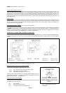
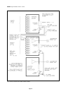
Power supply change-over
This function is carried out automatically and instantaneously upon failure of the regular AC mains supply. There is no break in
service and all facilities are retained (except battery charging), for the duration of the condition. Upon reinstatement of the AC
supply, the amplifier automatically reverts to AC operation and battery charging re-commences.
The change-over process may be monitored by making use of the power supply failure monitoring relay contact mentioned above.
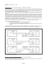
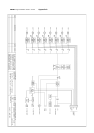
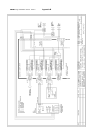
See Fig. 10 above, for clarification.
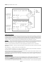
Battery charger circuit
Units except mixers provide trickle charge facilities for use with standby batteries connected to an AC mains/DC amplifier. Output
is in the form of a 0.5 second pulse at 1 second intervals and is controlled from the Power Management Board, (PMB.1, etc.). Low
AC mains input supplies will adversely effect the charge rate.
If, however, the charging facility is not required - perhaps because the battery system provides its own dedicated charger - then it
is preferable to disable the amplifier charger by cutting the red wire link at the end of the heat-sink type power resistor attached to
the Power Management Board heatsink plate. See APPENDIX D for identification of this link.
EARTHING AND HUM LOOPS
In all systems it is possible to inadvertently set up a hum loop. Each manufacturer has different methods of earthing his equipment
and so lack of familiarity with them may result in problems. A loop will manifest itself as a low level soft hum at either 100Hz or
50Hz which is not generally effected in tonal or amplitude content by any user or adjustment controls. There are many potential
earth loop paths in any system, but the larger the system, the more they are compounded, and resolving the problem can be
extremely exasperating unless a disciplined and logical approach is used.
Each system must be considered separately although rules of thumb do apply. Generally an audio loop will be set up wherever
two points in an audio system are interconnected by two earth paths. The resulting circuit will act as a turn in a transformer, with
any stray magnetic fields setting up resultant electrical currents in it. These currents are superimposed on whatever currents are
intentionally there, and these may be very low level audio signal currents.
However, the electronic circuitry within the chassis is earthed to chassis independently of the electrical safety earth by means of
a wire link or a 220 ohm resistor - dependent upon the unit - adjacent to the mixer facility socket. This provides earthing to prevent
self-oscillation whilst avoiding any tendency to cause earth loop problems. (See also the preceding sections covering the Mains
power input and DC power input requirements).
In designing the MACRO system, we have borne in mind that the applications for the equipment will generally be in large scale
installations where there may be many conflicting requirements. Therefore MACRO amplifier chassis are always earthed via the
power input connections.
********* THIS IS A SAFETY EARTH AND MUST NEVER BE DISREGARDED. ***********
Particular care should be taken when terminating the Locking DIN input plugs, as the cable clamp will connect with the plug body
on assembly and thence with the amplifier rear panel on insertion. Thus, if the signal cables audio screen is connected both to the
clamp and to pin 2, a loop will result. Similarly with the mixer facility connector. Aim to earth each amplifier fully in one place only,
with interconnection of amplifiers or ancillary equipment via input modules featuring transformer input circuitry, - for example L.24
to L32. These may be wired in a fully floating mode thus providing full isolation. Connect the audio screen of a signal cable to a
signal earth at one end only.
Bear in mind, also that with DC powered systems, the signal earth of each amplifier will be connected to the -ve terminal of the DC
supply. If that is already unavoidably earthed, it dictates that it must be the central earthing point of the system.
FACTORY FITTED OPTIONS
TB/ALC Automatic audio level control (ALC)
TB/S Loudspeaker line surveillance facility
MAC/LT Balanced line input for slave amplifiers
Free-standing cased units - specified only for earlier models. Originally Mustang product code FS.3U
Current amplifiers specified as rack mounting or free-standing.
A wrap-round sleeve case can only be factory fitted to a MACRO unit. A rack mounting unit, once shipped, cannot be fitted with
such a case due to the design of front panel being different for rack and free-standing versions.