


TLW-300SS DC WELDER/ AC GENERATOR— OPERATION AND PARTS MANUAL— REV. #2 (04/07/10) — PAGE 21
TLW-300SS — CONTROLS AND INDICATORS
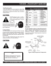
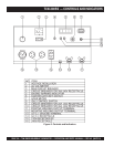
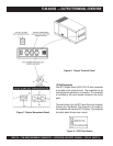
Figure 5 shows the location of the controls and indicators. The
functions of each control or indicator is described below.
1. Voltage Regulator- Controls the Voltage for welding/load.
2. AC Voltmeter- Indicated amount of voltage output.
3. Main Circuit Breaker- 2-pole, 42A will shut down current
when welder/generator is overloaded.
4. No. 1 Circuit Breaker-(S/N 5308737~)- single pole circuit
breaker will shut down current in the 240V/30A receptacle.
5. Ignition Switch with Key- Used to start and preheat engine.
6. Engine Warning Indicators- Lights red when the following
conditions occur:
7. Hour Meter – Indicates number of hours machine has
been in use or hours engine was run.
8. Idle Switch- Turn on for rpms to automatically adjust rpms
when a load is added.
9. No. 3 Circuit Breaker-(S/N 5308737~)- single pole circuit
breaker will shut down current in the 120V/20A receptacle.
10. No. 2 Circuit Breaker-(S/N 5308737~)- single pole circuit
breaker will shut down current in the 120V/30A receptacle.
11. Positive Welding Output Terminal- Positive connection
for welding.
12. Negative Welding Output Terminal-Negative connection
for welding.
13. G.F.C.I. Ground Terminal- Used to ground GFCI
receptacle.
14. G.F.C.I. Receptacle- 120V/20A receptacle for smaller
power applications.
15. 120V Receptacles- used for 20 or 30 amp power
applications.
16. 240V Receptacle- used for 30 amp power applications.
Low Oil Pressure
High Water Temperature
Electrical System Is Not Charging Properly