


PAGE 30 —KD1800/KD6 A.C. GENERATOR— PARTS & OPERATION MANUAL — REV. #1 (06/16/05)
KD1800/KD6 — MAINTENANCE (GENERATOR)
Generator
Capacitor Regulation
A single capacitor is used to regulate the voltage to within
5% of the rated load.
z
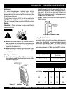
ALWAYS USE EXTREME CAUTION when handling
capacitors. The capacitor will still contain a high voltage
even after the engine has been shut-down.
z
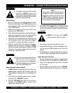
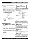
ALWAYS discharge the capacitor before handling. Use
a conductor or a screwdriver (Figure 15) with an insulated
handle. Place screwdriver across both capacitor
terminals while holding onto the handle. This will short
out the voltage and discharge the capacitor.
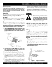
Checking the Charge of the Capacitor
1. Use an
"OHMMETER"
to check the
charge
and
discharge
of the capacitor. Set the ohmmeter to the
RX-1000 scale.
2. Place the ohmmeter leads on the capacitor terminals
one at a time. A meter deflection should be seen
(charging), followed by a slow return to infinity
(discharging).
3. Reverse the ohmmeter leads and repeat the procedure.
The results should be the same. Replace the capacitor
if no meter deflection or continuity has been indicated
by the ohmmeter.
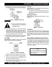
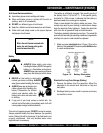
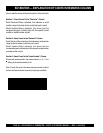
Flashing Rotor Procedure
1. Disconnect all incoming power leads to the generator.
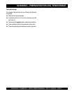
2. Connect the (+) lead of a 12 volt battery to the "R"
connection (Figure 16).
Figure 15. Discharging Capacitor
3. Connect the (-) lead of the battery to the rotor shaft.
4. Re-connect all incoming power leads to the generator
5. Start the generator as outlined in the
"Operating
Section"
of this manual.
6. With a voltmeter check the no load voltage at the 120/
240 output connector located on the control box.
7. The no load should be within 10% of the rated load.
8. If residual voltage is normal, the capacitor is defective
and should be replaced.
Diode Check
1. Check the diode individually by removing the (+)
rotor
lead stud
connection (Figure 16). The diode is good if
the resistance reading is approximately mid -scale on
the lowest ohm scale.
2. Check for leakage in the diode by reversing the polarity.
The diode is good if the resistance reading is
infinite
.
3. A faulty diode will give a resistance value of
zero
.
Figure 16. Flashing The Rotor Configuration
DO NOT
run the generator during this
procedure.
NOTE