


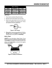
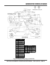
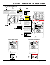
GAC9.7HZ 60 HZ GENERATOR • OPERATION AND PARTS MANUAL — REV. #2 (03/31/10) — PAGE 29
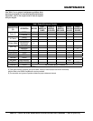
GENERATOR WIRING DIGRAM
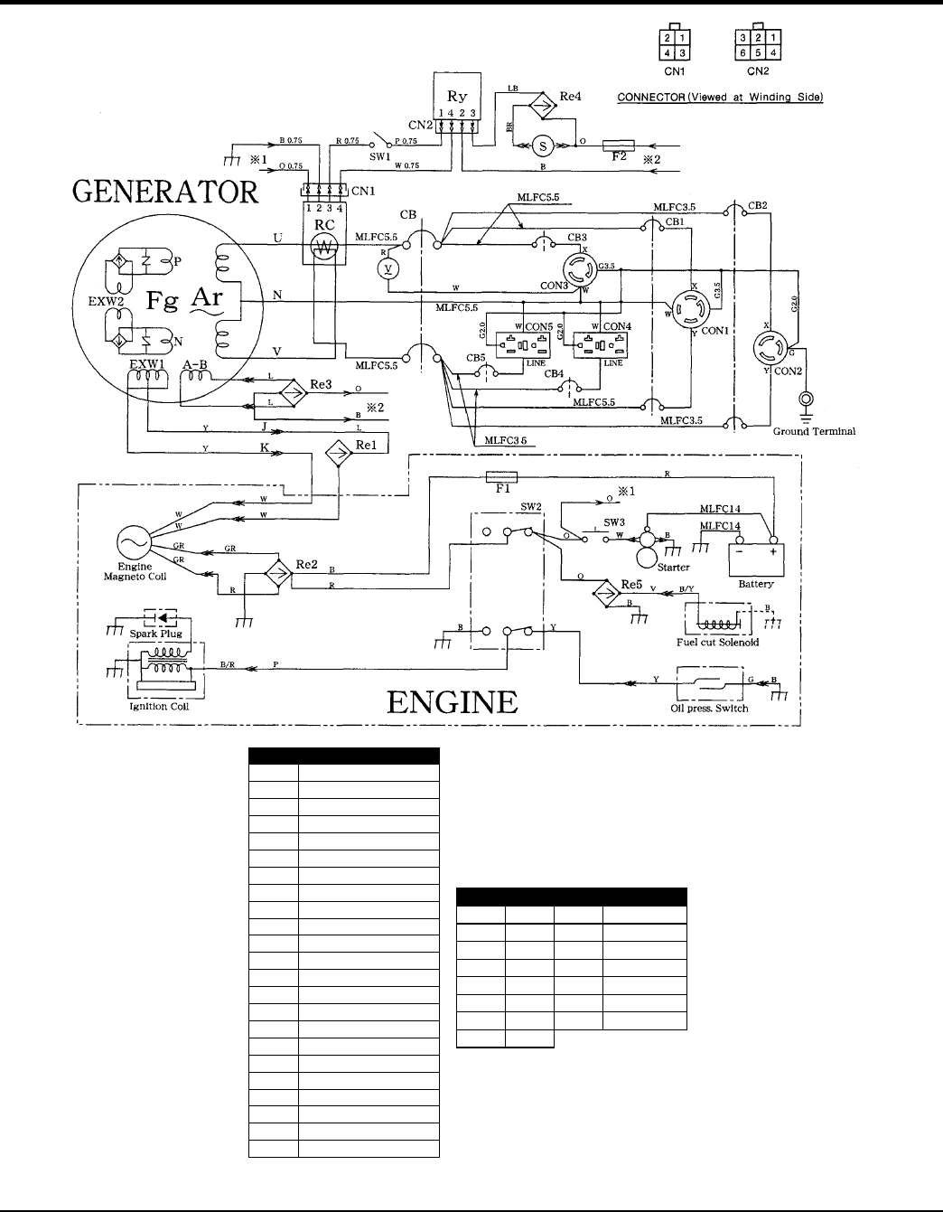
Figure 33. Generator Wiring Diagram (GAC9.7HZ)
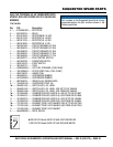
SYMBOL PART NAME
Ar Armature Winding
Fg Field Winding
EXW1~2 Excitation Winding
V AC Voltmeter (120/240)
Re1~5 Rectifier
CON1 Receptacle L14-30R
CON2 Receptacle L6-20R
CON3 Receptacle L5-30R
CON4~5 Receptacle 5-15R
CB UPM-2 35A
CB1 CP-32E/30N 30A
CB2 CP-32E/20N 20A
CB3 CP31E/30N 30A
CB4~5 CP-31E/15N 15A
SW1 Idle Control Switch
SW2 Operation Switch
SW3 Starter Switch
RC Idle Control Device
S Idle Control Solenoid
RY Relay
F1~F2 Fuse
GR Ground Terminal T-3830
C Capacitor
Wiring Color Code
Symbol Color Symbol Color
B BLACK R RED
L BLUE W WHITE
BR BROWN Y YELLOW
G GREEN LB LIGHT BLUE
GR GRAY LG LIGHT GREEN
V VIOLET O ORANGE
P PINK