


PAGE 16 — GA-4.5R/GA-4.5RA A.C. GENERATOR— OPERATION & PARTS MANUAL — REV. #1 (11/27/06)
GA-4.5R/GA-4.5RA — CONTROLS AND INDICATORS
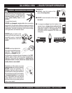
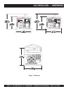
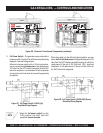
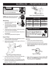
Figure 2C. Full Power Switch 120VAC (Up)
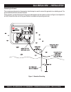
Simplified Wiring Diagram
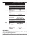
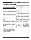
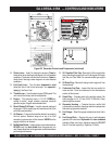
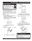
Figure 2D. Full Power Switch 120/240 VAC (Down)
Simplified Wiring Diagram
11. Full Power Switch – The generators are provided with a
full power switch. Figures 2C and 2D show simplified wiring
diagrams of the dual voltage system.
When the full power switch is in the 120 volt (up) position,
you can access the
full rated power
of the generators at
120 volts from the GFCI duplex receptacle and the120V
twist-lock receptacle, or a combination of both receptacles
as long as the total load does not exceed the generating
set capacity.
When the switch is in the 240 volt (down) position, you can
acess
half of the rated power
of the generating set at 120
volts from the GFCI duplex receptacle and up to half of the
rated power of the set at 120 volts from 120V twist-lock
receptacle; or full rated power of the set at 240 volts from
the 240V twist-lock receptacle.
When the
full power switch
is in the
120V position, the 240V twist-lock
receptacle
cannot be used
.
NOTE
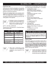
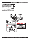
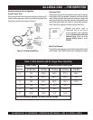
Figure 2B. Generator Controls and Components (continued)