


DCA-400SPK — PARTS AND OPERATION MANUAL — REV. #0 (06/19/01) — PAGE 49
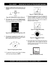
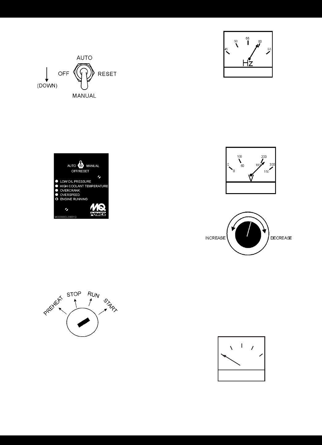
10. The generator's frequency meter (Figure 41) displays
the 60 cycle output frequency in HERTZ.
Figure 41. Frequency Meter (Hz)
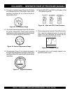
Figure 42. Voltage Meter (Volts)
11. The generator's voltage meter (Figure 42) displays the
120 VAC in VOLTS. If the voltage is not within the
specified frequency tolerance, use the voltage
adjustment control knob (Figure 43) to increase or
decrease the desired voltage.
A
0
40
60
75
20
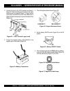
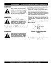
Figure 44. Ammeter (No Load)
Figure 43. Voltage Adjust Control
Knob
12. The ammeter (Figure 44) will indicate zero amps with no
load applied. When a load is applied, this meter will
indicate the amount of current that the load is drawing
from the generator’s alternator.
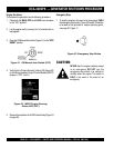
Figure 38. Off/Manual/Auto Switch (Manual)
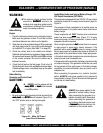
8. After engine starts, verify that the "Engine Running"
status LED (Figure 39) on the Microprocessor Engine
Control Module (MPEC) display is "ON" (lit).
Figure 39. MPEC Engine Running Status LED
7. Place the Off/Manual/Auto switch (Figure 38) in the
MANUAL position (down). Observe that the engine begins
to crank.
Figure 40. Engine Ignition Switch
9. If the generator is equipped with a ignition switch, turn
the key to “Start” position (Figure 40). Once the engine
starts, release the key to the “on” position.
DCA-400SPK — GENERATOR START-UP PROCEDURE (MANUAL)