


PAGE 34 — DCA-25USIXF/DCA-25USI2XF — OPERATION AND PARTS MANUAL — REV. #8 (05/08/09)
DCA-25USIXF/DCA-25USI2XF— GENERATOR START-UP PROCEDURE
The engine's exhaust contains harmful emissions.
ALWAYS have adequate ventilation when operating
.
Direct exhaust away from nearby personnel.
Before Starting
CAUTION - LETHAL EXHAUST HAZARD
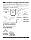
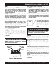
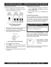
2. In warm weather conditions, skip to step 3. Preheat the
engine
glow plugs
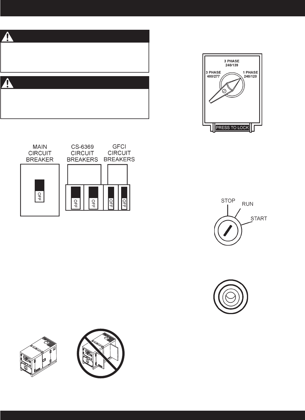
by turning the ignition key
(Figure 41) to the RUN position. When the preheat lamp
(Figure 42) illuminates, proceed to step 3.
Figure 42. Pre-Heat Indicator Lamp
Figure 41. Ignition Switch Pre-Heat
(Run Position)
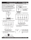
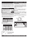
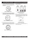
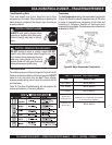
1. Place the
voltage selector switch
in the desired voltage
position (Figure 40).
Figure 40. Voltage
Selector Switch
INCORRECTCORRECT
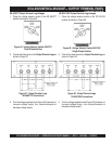
2. Connect the load to the
receptacles
or
the
Output
Terminal Lugs
as shown in (Figure 11). These load
connection points can be found on the output terminal
panel and the output terminal panel’s hard wire hookup
panel.
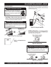
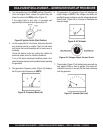
3. The output terminal lugs are protected by a plastic cover.
Remove this cover to gain access to the terminals.
Tighten terminal nuts securely to prevent load wires from
slipping out.
4. Close all engine enclosure doors (Figure 39).
Figure 39. Engine Enclosure Doors
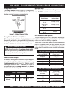
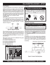
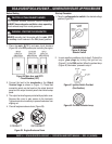
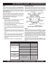
1. Place the
main, G.F.C.I.,
and
aux.
circuit breakers
(Figure 38) in the OFF position prior to starting the engine.
Figure 38. Main, Aux. and GFCI
Circuit Breakers (OFF)
NEVER!
manually start the engine with the
main
,
GFCI
or
auxiliary
circuit breakers in the ON (closed) position.
WARNING - STARTING THE GENERATOR
Start-up
Procedure