


DCA-25USIXF/DCA-25USI2XF — OPERATION AND PARTS MANUAL — REV. #1 (05/08/09) — PAGE 35
1
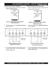
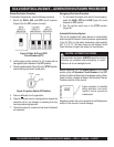
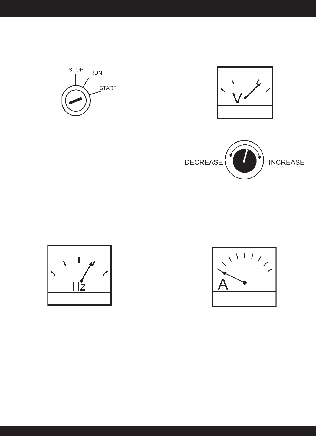
Figure 46. Voltage Adjust Control Knob
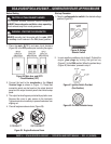
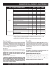
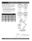
Figure 47. Ammeter (No Load)
7. The ammeter (Figure 47) will indicate zero amps with no
load applied. When a load is applied, this meter will
indicate the amount of current that the load is drawing
from the generator.
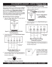
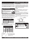
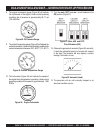
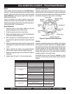
5. The generator's frequency meter (Figure 44) displays
the 60 cycle output frequency in HERTZ.
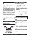
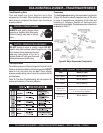
6. The generator's AC-voltmeter (Figure 45) displays the
output voltage in VOLTS. If the voltage is not within the
specified frequency tolerance, use the voltage adjustment
control knob (Figure 46) to increase or decrease the
desired voltage.
Figure 45. AC Voltmeter
Figure 44. Frequency Meter (Hz)
4. Let the engine idle for 3-5 minutes, listen and check for
any abnormal sounds or smells. Check for fuel leaks,
and noises that would associate with a loose cover or
hardware.
Check the electric motor fan cooling the radiator for
abnormal speed, sound or vibration conditions.
If any of the above mentioned conditions exists, shut-
down the engine and correct the problem before operating
the generator.
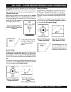
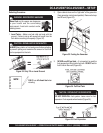
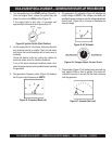
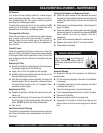
3. Turn the ignition key to the START position (Figure 43).
Once the engine starts, release the ignition key and
allow it to return to the RUN position (Figure 41).
If the engine fails to start after 10 seconds, wait
approximately 30 seconds and repeat steps 2-3.
Figure 43. Ignition Switch (Start Position)
DCA-25USIXF/DCA-25USI2XF— GENERATOR START-UP PROCEDURE