


DCA-25USIXF/DCA-25USI2XF — OPERATION AND PARTS MANUAL — REV. #1 (05/08/09) — PAGE 27
1
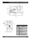
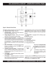
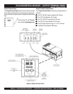
DCA-25USI — GAUGE READING/ TERMINAL PANEL CONNECTIONS
The gauges and selector switches on the control panel
DO NOT effect the generator output. They are provided to
help observe how much power is being supplied at the
Output terminals lugs
.
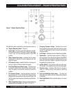
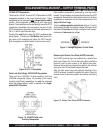
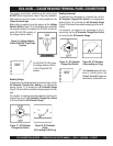
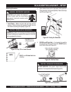
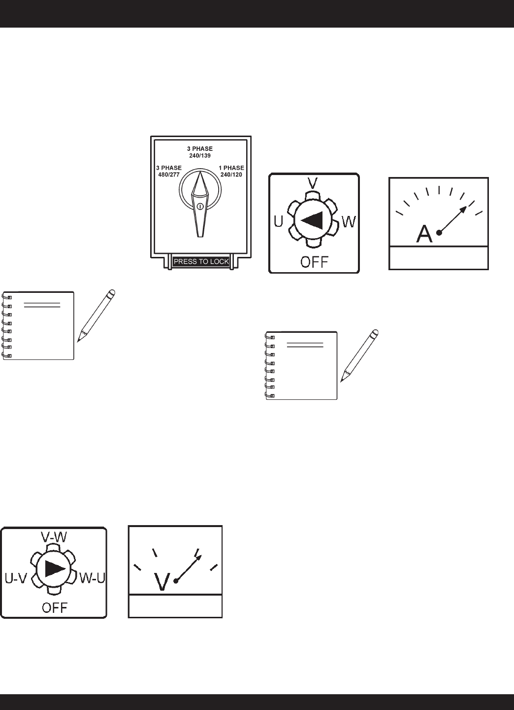
Before taking a reading from either gauge, set the
Voltage
Selector Switch
(Figure 16) to the position which produces
the required voltage (For example, for 3Ø 240V, choose the
center 3Ø 240/139V position on
the voltage selector switch.)
Figure 16. Voltage Selector
Switch 240/139V Three Phase
Position
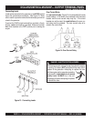
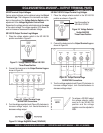
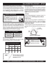
Figure 17. AC Voltmeter
Change-Over Switch
Figure 18. AC Voltmeter
Gauge
(Volt reading on W-U Lug)
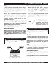
Figure 20. AC Ammeter
(Amp reading on U lug)
Figure 19. AC Ammeter
Change-Over Switch
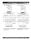
Reading Amperage
To determine the amperage at a terminal lug, set the
AC Ammeter Change-Over
Switch
to the appropriate
setting (Figure 19) to activate the
AC Ammeter Gauge
(Figure 20 and read the available amperage at the termi-
nal lug.
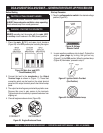
For example, to measure the amperage at the U
terminal lug, set the
AC Ammeter Change-Over Switch
to U and read the AC Ammeter Gauge.
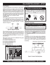
For 3Ø 208V/1Ø,120V, place
the Voltage Selector Switch
in the 3 Phase 240/139
position.
NOTE
The
ammeter
gauge will only
show a reading when the
Output Terminal Lugs
are
connected to a load and in use.
NOTE
Reading Voltage
To determine the voltage between two terminal lugs, set the
AC Voltmeter Change-Over
Switch
to the appropriate
setting (Figure 17) to activate the
AC Voltmeter Gauge
(Figure 18) and read the available voltage between the two
lugs.
For example, to measure the voltage between the W and U
terminal lugs, set the
AC Voltmeter Change-Over Switch
to W-U and read the
AC Voltmeter Gauge
.