PAGE 28 — DCA-180SSV— OPERATION AND PARTS MANUAL — REV. #1 (04/14/10)
DCA-180SSV — GENERATOR OUTPUTS
Generator Amperage
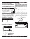
Tables 8 and 9 describe the generator’s current output capa-
bility for both 1Ø-phase and 3Ø phase applications.
elbaliavAsegatloV.7elbaT
esahPeerhT
)elbahctiwS(
V802V022V042V614V044V084
esahPelgniS
)elbahctiwS(
V021V721V931V042V452V772
Generator Output Voltages
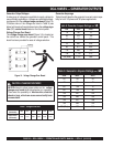
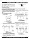
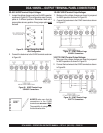
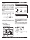
A wide range of voltages are available to supply voltage for
many different applications. Voltages are selected by apply-
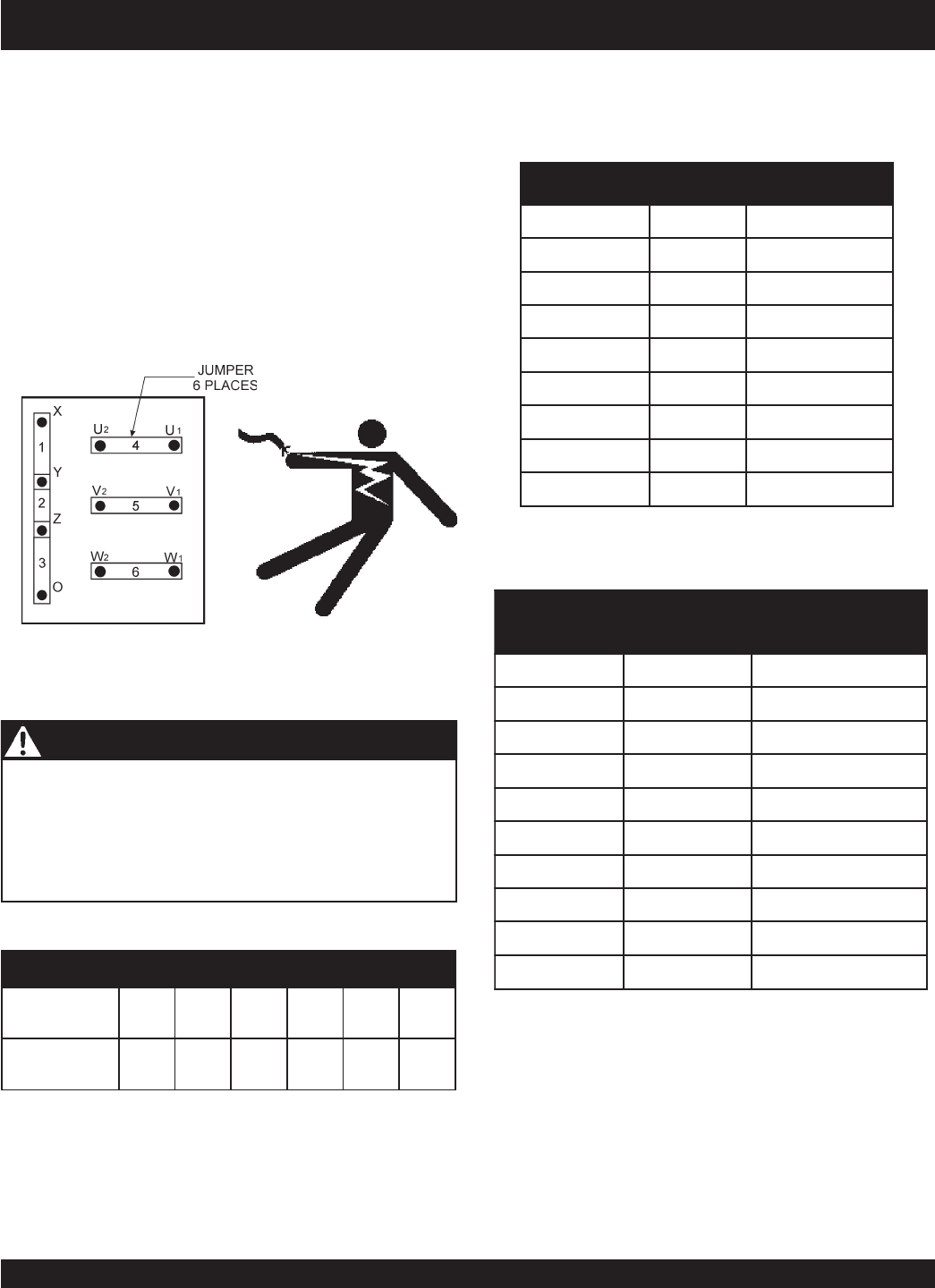
ing jumpers (6) to the
voltage change-over board
(Figure 14).
To obtain some of the voltages as listed in Table 6 (see
below) will require a fine adjustment using the
voltage regu-
lator
(VR)
control knob
located on the control panel.
Voltage Change-Over Board
The
voltage change-over board
(Figure 14) is located on
the control box, behind the generator control panel. This
board has been provided for ease of voltage selection.
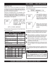
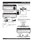
CAUTION - CHANGING VOLTAGES
NEVER attempt to place jumper plates on the
voltage
change-over board
while the generator is in operation.
There exist the possibility of
electrocution, electrical
shock or burn, which can cause severe bodily harm
or even death
!
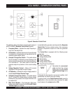
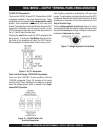
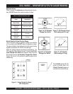
Figure 14. Voltage Change-Over Board
sgnitaRerepmArotareneG.8elbaT
⎯⎯
⎯
⎯⎯
1
∅∅
∅
∅∅
WkV021V042
8105157
83613851
85384762
87056632
89718294
811389913
831051,1575
)xaM(851713,1856
sgnitaRerepmArotareneG.9elbaT
⎯⎯
⎯
⎯⎯
3
∅∅
∅
∅∅
AVKV042V084
028442
046984
0644127
0829169
001142021
021982441
041733861
061483291
)xaM(081334612


