


6
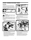
IMPORTANT:
The cable should have very little slack, but
should NOT be tight. An overtightened cable may
prohibit the auger and drive from disengaging.
WARNING: Over-tightening the cable may
prohibit the auger and drive from disengaging
and compromise the safety of the snow
thrower. Do NOT overtighten the cable.
• Once properly adjusted, tighten the jam nut against
the coupling end of the cable to lock it in position.
Refer to Auger Control Test on page 9 prior to operating
your snow thrower. Read and follow all instructions
carefully and perform all adjustments to verify your
snow thrower is operating safely and properly.
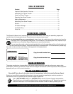
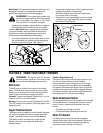
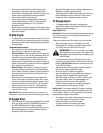
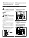
• If not already attached, slip the cables that run from
the handle panel to the chute into the cable guide
located on top of the engine. See Figure 5.
Figure 5
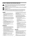
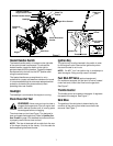
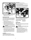
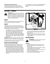
• Unwrap the headlight wire, which is attached to the
headlight beneath the handle panel.
• Wind the headlight wire around the right handle
until excess slack is removed.
• Plug the wire from the headlight into the wire lead
coming from the right side of the engine, beneath
the fuel tank. See Figure 6.
Figure 6
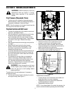
SECTION 3: KNOW YOUR SNOW THROWER
WARNING: Be familiar with all controls
and their proper operation. Know how to stop
the machine and disengage them quickly.
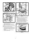
Shift Lever
The shift lever is located in the center of the handle
panel. The shift lever may be moved into one of eight
positions. Run engine with throttle in the fast position.
Use the shift lever to determine ground speed.
Forward: There are six speeds. Position one (1) is the
slowest. Position six (6) is the fastest.
Reverse: There are two reverse (R) speeds R1 and R2.
The “R2” closest to the operator (all the way back) is the
faster of the two.
Auger/Traction Control
The auger control is located on the left handle. Squeeze
the control to engage the augers; release to stop the
augers. The traction control must also be released.
The traction control is located on the right handle.
Squeeze the control to engage the wheel drive.
Release to stop.
Traction / Auger Control Lock
This same control also locks the auger control so you
can turn the chute directional control without
interrupting the snow throwing process. If the auger
control is engaged with the traction control engaged,
the operator can release the auger control (on the left
handle) and the augers will remain engaged. Release
the traction control to stop both the augers and wheel
drive (auger control must also be released).
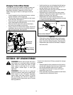
Chute Directional Control
The chute directional control is located on left hand side
of the snow thrower.To change the direction in which
snow is thrown, rotate chute directional control as
follows:
• Clockwise to discharge to the left.
• Counterclockwise to discharge to the right.
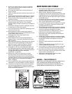
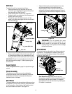
Chute Tilt Control
The distance snow is thrown can be changed by
adjusting the angle of the chute assembly. Move the
chute tilt control forward to decrease the distance,
toward the rear to increase. See Figure 7.
Cable Guide
Lower Handle
Alternator Lead
Lamp Wire