


9
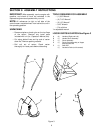
Figure 11
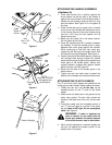
Figure 12
IMPORTANT
:
Attach the shift rod and clutch cables
as follows. THEN CHECK THE ADJUSTMENTS AS
INSTRUCTED, AND MAKE ANY FINAL ADJUST-
MENTS NECESSARY BEFORE
OPERATING YOUR
SNOW THROWER. Failure to follow the instructions
may cause damage to the snow thrower.
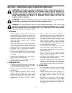
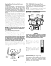
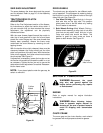
ATTACHING THE SHIFT ROD (Hardware D)
1. Place the shift lever (on the handle panel) in the
sixth (6) speed position (all the way forward).
2. Place the bent end of the shift rod (E) into the
hole in the shift arm assembly. See Figure 11.
Secure with flat washer and hairpin clip.
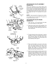
3. Start threading the ferrule onto the other end of
the shift rod. Push down on the shift rod (and shift
arm assembly) as far as it will go.
4 Thread the ferrule onto the shift rod until the fer-
rule lines up with the
upper
hole in the shift lever
(beneath the handle panel). Insert the ferrule into
the upper hole in the shift lever from the left side
when adjustment is correct. Secure with flat
washer and hairpin clip.
Make certain to check for correct adjustment of the
shift rod as instructed in the Final Adjustment section
before operating the snow thrower.
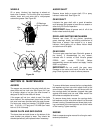
FINAL ADJUSTMENTS
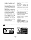
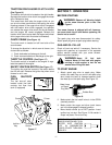
Auger Drive Clutch
To check the adjustment of the auger drive clutch,
push forward on the left hand clutch grip (depress the
rubber bumper). There should be slack in the cable.
Release the clutch grip. The cable should be straight.
Make certain you can depress the auger drive clutch
grip against the left handle completely.
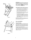
If necessary, loosen the hex jam nut and thread the
cable in (for less slack) or out (for more slack) as nec-
essary. Refer to Figure 12. Recheck the adjustment.
Tighten the jam nut against the cable when correct
adjustment is reached.
Shift
Rod
Shift
Arm
Assembly
Washer
Flat
Hairpin
Clip
Traction
Drive
Clutch
Shift Lever
Ferrule
“Z” End
Hex Jam
Nut
Cable is Straight