


8
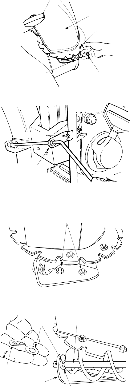
Figure 7
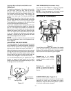
Figure 8
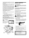
Figure 9
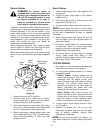
Figure 10
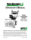
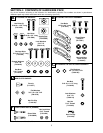
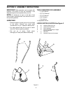
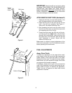
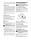
ATTACHING THE CHUTE ASSEMBLY
(Hardware B)
Place chute assembly (C) over chute opening, with
the opening in the chute assembly facing the front of
the unit. Place chute flange keepers beneath lip of
chute assembly, with the flat side down. Secure with
hex head screws and hex lock nuts as shown in Fig-
ure 7. Tighten with two 7/16" wrenches. Do not over-
tighten.
NOTE:
Locknuts cannot be threaded onto a bolt by
hand. Tighten with 2 7/16” wrenches. This type of nut
is used where vibration occurs.
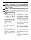
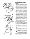
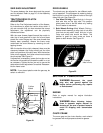
ATTACHING THE CHUTE CRANK
(Hardware C)
1. Insert hex bolt 1-1/2" long through the upper
chute crank bracket (D). See Figure 8.
2. Place the hex bolt into the hole provided in the
left handle. Secure with lock washer and hex nut.
Do not tighten until after attaching the other end
of the chute crank.
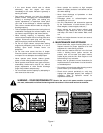
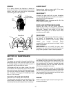
3. To align the spiral on the chute crank, it may be
necessary to loosen the carriage bolts and hex
lock nuts which secure the lower chute crank
bracket to the extension on the left side of the
chute assembly. See Figure 9.
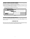
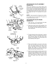
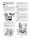
4. Place one flat washer on the end of the chute
crank, then insert the end of the crank into the
hole in the plastic bushing in the chute crank
bracket. See Figure 10. Place another flat
washer on the end of the chute crank, and insert
hairpin clip into hole in the end of crank.
5. Adjust the chute bracket so that the spiral on the
chute crank fully engages the teeth on the chute
assembly. Tighten the nuts on the lower chute
crank bracket securely. Tighten the hex bolt and
nut on the upper chute crank bracket on the
handle.
Chute
Assembly
Hex Head
Screw
Hex Lock
Nut
Chute
Flange
Keeper
Chute
Crank
Bracket
Hex Bolt
Lock Washer
Hex Nut
Upper
Carriage Bolts
Hex Lock Nuts
Flat
Washers
Lower
Chute Crank
Bracket
Hairpin Clip
Chute
Crank
Plastic
Bushing