


3
9
Tractor Set-Up
NOTE: This Operators Manual covers a range of product
specifications for various models. Characteristics and features
discussed and/or illustrated in this manual may not be applicable
to all models. MTD LLC reserves the right to change product
specifications, designs and equipment without notice and
without incurring obligation.
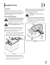
Connecting the Battery Cables
CALIFORNIA PROPOSITION 65 WARNING:
Battery posts, terminals, and related accessories
contain lead and lead compounds, chemicals known
to the State of California to cause cancer and
reproductive harm. Wash hands after handling.
CAUTION: When attaching battery cables, always
connect the POSITIVE (Red) wire to its terminal first,
followed by the NEGATIVE (Black) wire.
For shipping reasons, both battery cables on your equipment
may have been left disconnected from the terminals at the
factory. To connect the battery cables, proceed as follows:
NOTE: The positive battery terminal is marked Pos. (+). The
negative battery terminal is marked Neg. (–).
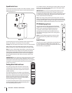
1. Remove the plastic cover, if present, from the positive battery
terminal and attach the red cable to the positive battery
terminal (+) with the bolt and hex nut. See Figure 3-1.
Figure 3-1
2. Remove the plastic cover, if present, from the negative
battery terminal and attach the black cable to the negative
battery terminal (–) with the bolt and hex nut. See Figure 3-1.
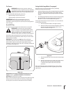
3. Position the red rubber boot over the positive battery
terminal to help protect it from corrosion.
NOTE: If the battery is put into service after the date shown on top/
side of battery, charge the battery as instructed in the Maintenance
section your Operator’s Manual prior to operating the tractor.
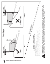
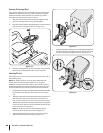
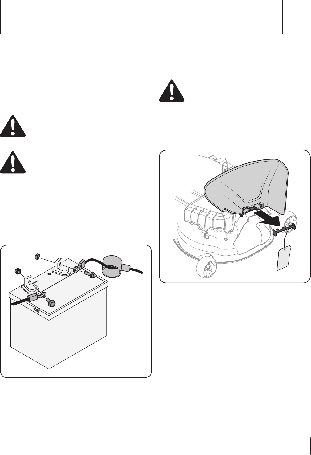
Lower Deck Discharge Chute Deflector
WARNING! Never operate the mower deck
without the chute deflector installed and in the
down position.
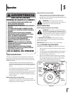
1. Check the mower deck for a shipping brace that may be
holding the chute deflector upward for shipment. If the
brace is present, it must be removed before operating the
tractor. Holding the chute deflector fully upward, remove
the shipping brace. Lower the chute deflector and discard
the shipping brace. See Figure 3-2.
Figure 3-2
Assembly & Set-Up
3
9