


9sectiOn 2 — asseMbly & set-up
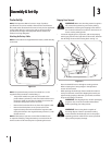
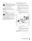
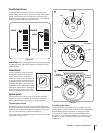
Attaching The Steering Wheel
If the steering wheel for your tractor did not come attached, the
hardware for attaching it has been packed within the steering
wheel, beneath the steering wheel cap. Carefully pry off the
steering wheel cap and remove the hardware.
With the wheels of the tractor pointing straight forward,
place the steering wheel over the steering shaft.
Place the washer (with the cupped side down) over the
steering wheel and secure with the hex bolt. See Fig. 3-3.
Place the steering wheel cap over the center of the steering
wheel and push downward until it “clicks” into place.
Attaching The Seat
Seat styles vary by tractor model and there are three different
styles available:
Standard Adjustment
Quick Adjustment
Knob Adjustment
If the seat for your tractor was not attached at the factory, refer
to Fig. 3-4, Fig. 3-5, and Fig. 3-6 to identify your tractor’s seat
style and follow the applicable instructions below to attach it.
NOTE: For shipping reasons, seats are either fastened to the
tractor seat’s pivot bracket with a plastic tie, or mounted
backward to the pivot bracket. In either case, free the seat
from its shipping position and remove the two hex screws (or
knobs, on models so equipped) from the bottom of seat before
proceeding with applicable instructions below.
1.
2.
3.
•
•
•
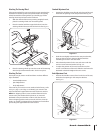
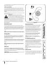
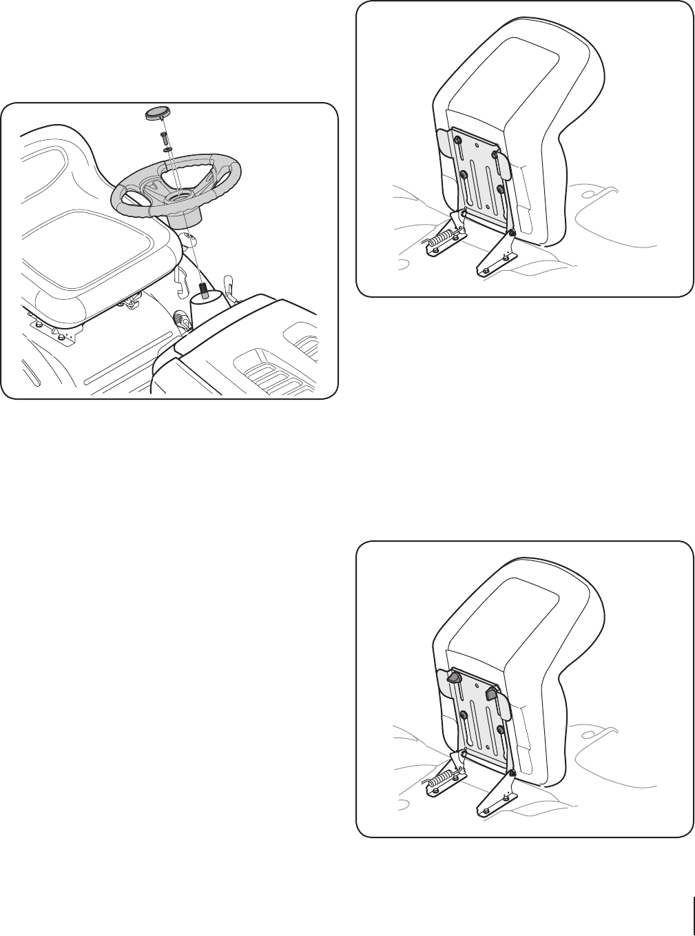
Standard Adjustment Seat
Position the shoulder screws (found on the base of the seat)
inside the slot openings in the seat pivot bracket. Fig. 3-4.
Slide the seat slightly rearward in the seat pivot bracket,
lining up the rear slots in the pivot bracket with the
remaining two holes in the seat’s base.
Select desired position for the seat, and secure with the
two hex screws removed earlier. See Fig. 3-4.
To adjust the position of the seat, loosen the two hex
screws on the bottom of the seat. Slide the seat forward or
backward as desired. Retighten the two screws.
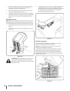
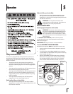
Knob Adjustment Seat
Position the shoulder screws (found on the base of the seat)
inside the slot openings in the seat pivot bracket.
See Fig. 3-5.
1.
2.
3.
4.
1.
Figure 3-3
Figure 3-4
Figure 3-5
9sectiOn 2 — asseMbly & set-up