


6
3
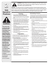
Always stop engine,
disconnect spark
plug, and ground
against engine before
cleaning, lubricating
or doing any kind
of maintenance or
adjustments on your
machine.
DO NOT LIFT
MACHINE WITH
CHUTE HANDLE.
NOTE: Never replace
the auger shear pins
with standard pins.
Any damage to the
auger gearbox or other
components, as a reult
of doing so, will NOT
be covered by your
snow thrower’s war-
ranty.
Never use your hands
to clean snow and
ice from the chute
assembly or auger
housing..
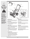
IMPORTANT: This unit is shipped WITH OIL and
WITHOUT GASOLINE. After assembly refer to
separate engine manual for proper fuel and engine oil
recommendations.
NOTE: Reference to right hand or left hand side of
machine are observed from the operating position.
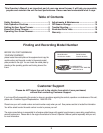
NOTE: This Operator’s Manual covers several
models. Snow thrower features vary by model. Not all
features discussed in this manual are applicable to all
snow thrower models.
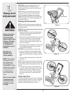
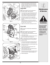
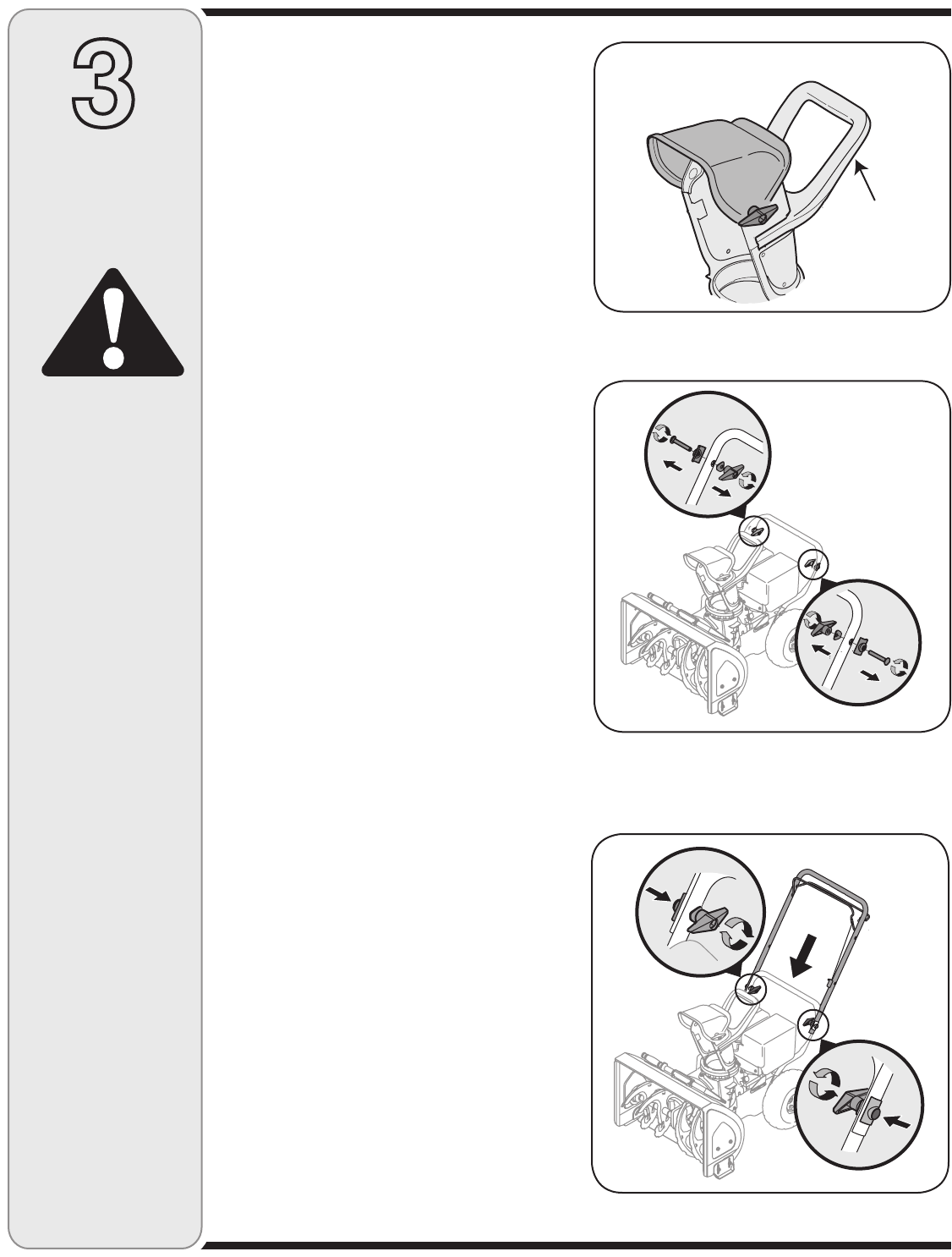
Setting Up The Handle
NOTE: Be aware of the three loosely fitted cable ties
attached to the lower handle that will be ustilizred later
to secure the cables.
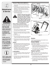
WARNING: Do not lift the snow thrower by the chute
handle. See Figure 1.
1. Loosen and remove the wing knob, saddle washer,
handle tab and carriage bolt on each side of the
lower handle. See Figure 2.
2. Slide one of the loosely fitted cable ties from the right
side of the lower handle up to the cross member
of the lower handle. Leave the second cable tie
in place on the right side of the lower handle. See
Figure 4. for reference.
3. Lift the upper handle up and position it over the lower
handle, aligning the holes where the wing knobs
were removed. See Figure 3.
CAUTION: Be careful not to bend or kink the cable.
4. Insert the carriage bolt from the outside through a
handle tab, the upper and lower handles, a saddle
washer and into the wing knob . Repeat on the other
side.
5. Tighten the wing knobs on each side of the handle.
See Figure 3.
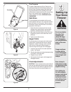
NOTE: Make sure that the drive cable is routed parallel
to the left upper handle, then across the top of the lower
handle and finally parallel to the right lower handle. See
Figure 4.
6. Three cable ties have been used to loosely tie the
two control cables to the lower handle. Two of these
cable ties are on each arm, and third on the top
cross bar of the lower handle. Tighten these cable
ties to secure the cable to the lower handle. See
Figure 4.
Clean-Out Tool
This tool and the electric extension cord, if so equipped,
may be fastened with a cable tie to the rear of the auger
housing for shipping purposes. In that case, cut the
cable tie and remove the extension cord now.
Setup And
Adjustment
WARNING
Figure 3
Figure 2
Figure 1
Chute Handle