


6
3
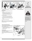
Setting Up
Your Snow
Thrower
NOTE: References to
right or left side of the
snow thrower are deter-
mined from behind the
unit in the operating
position.
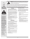
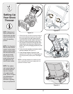
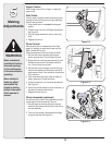
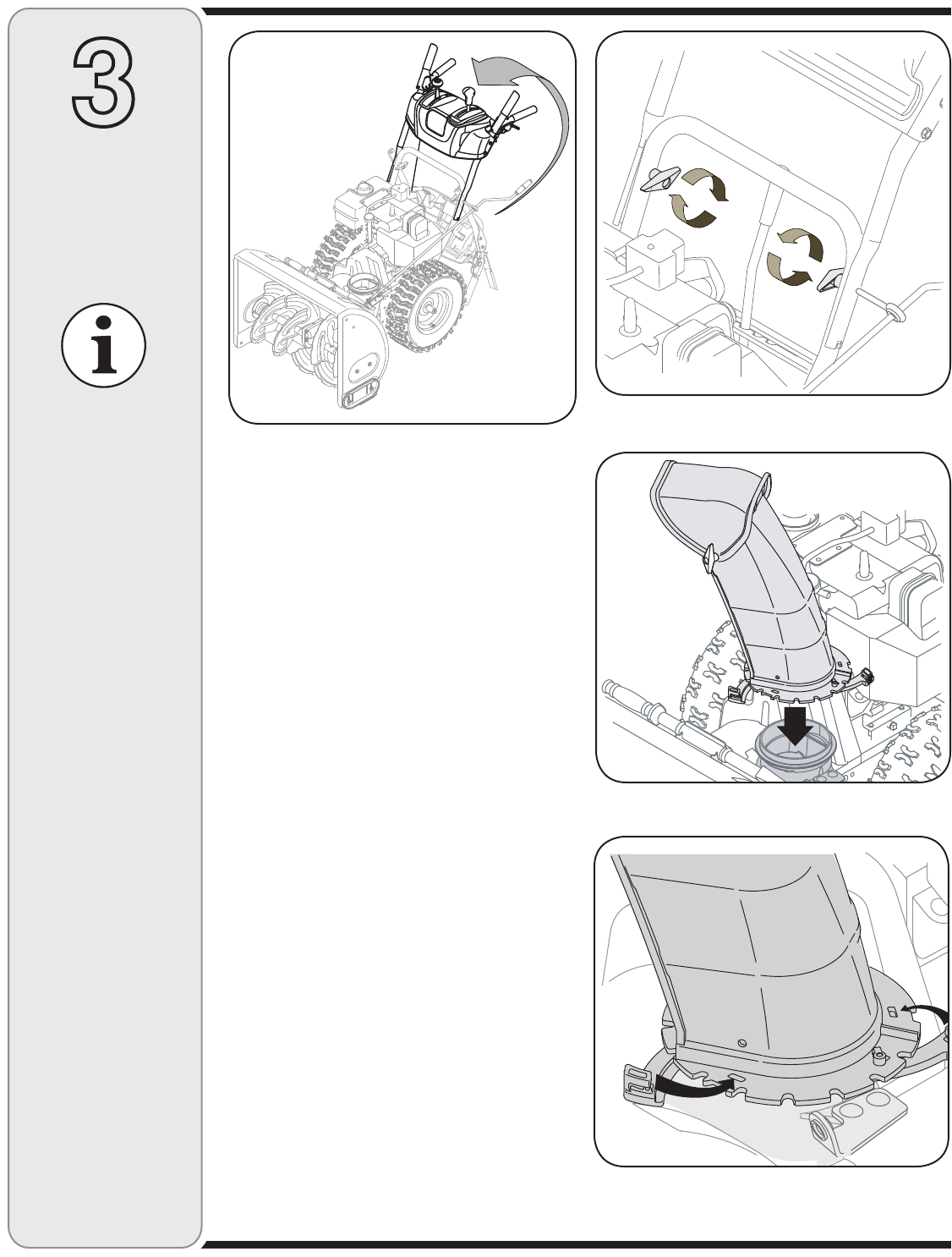
1. Observe the lower rear area of the snow thrower to
be sure both cables are aligned with roller guides.
Pull up and back on the upper handle, align the
upper handle with the lower handle. See Figure 3-1.
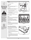
2. Secure the handle by tightening the plastic wing
knob located on both the left and right sides of the
handle. Remove and discard any rubber bands, if
present. They are for packaging purposes only. See
Figure 3-2.
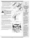
3. Position the chute assembly over the base, seated
securely on adapter. See Figure 3-3.
4. Close the flange keepers to secure the chute
assembly to the chute base. The flange keepers will
click into place when properly secure. See Figure
3-4.
NOTE: If the flange keepers will not easily click into
place, use the palm of your hand to apply swift, firm
pressure to the back of each.
NOTE: Two replace-
ment auger shear pins
are included with this
manual (or stowed
in the plastic handle
panel). Refer to Augers
in the Maintainance
Section for more
information regarding
shear pin replacement.
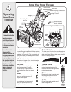
NOTE: This Operator’s
Manual covers several
models, handle panels,
lights and chute cranks
are some features that
may vary by model.
Not all features refer-
enced in this manual
are applicable to all
snow thrower models.
Figure 3-2
Figure 3-3
Figure 3-4
Figure 3-1