


7
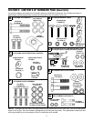
Assembly (Crated Unit)
WARNING: Disconnect the spark plug
wire and ground it against the engine to
prevent unintended starting.
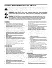
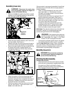
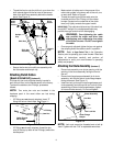
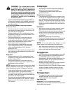
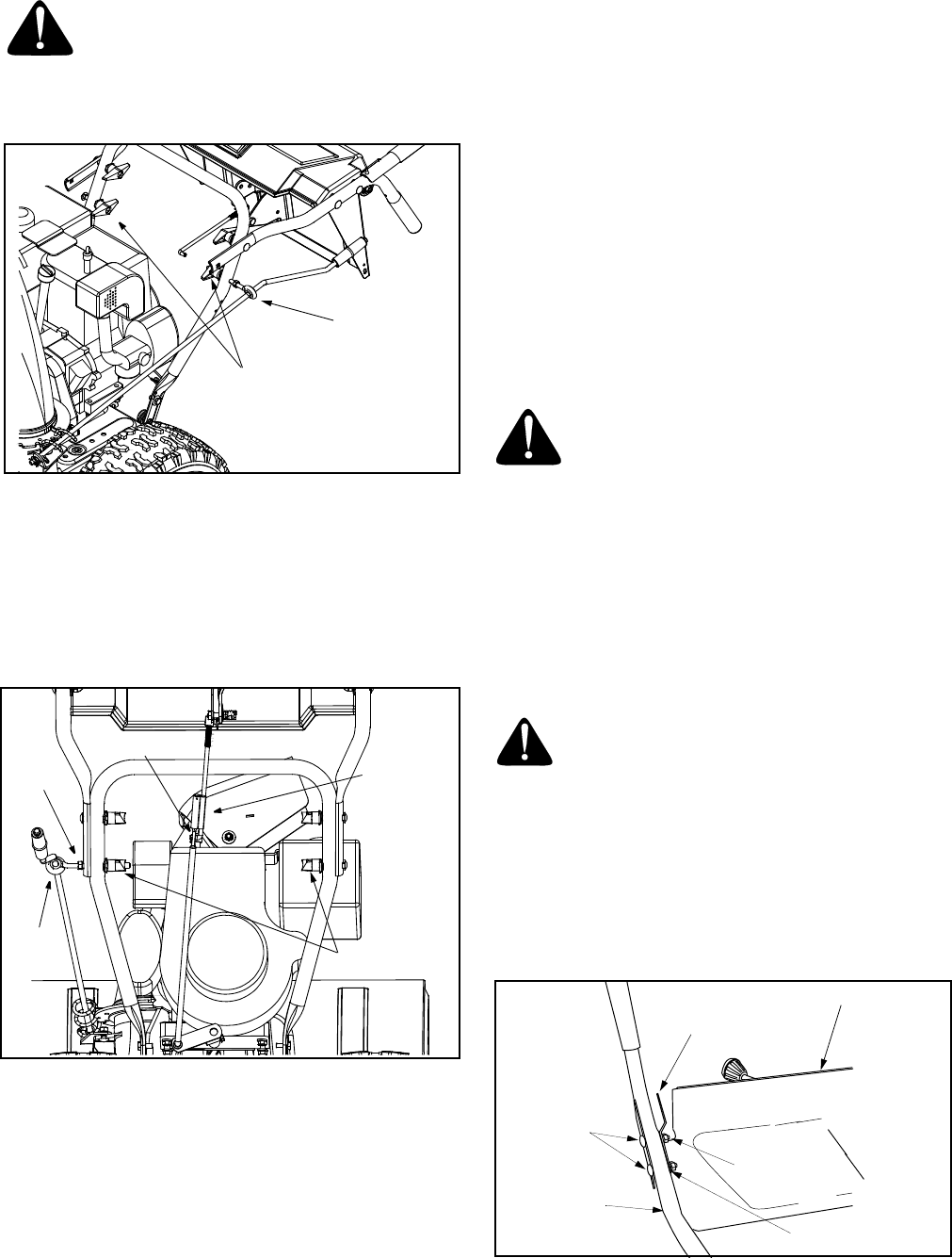
• Remove the lower two plastic wing knobs, cupped
washers and carriage bolt (eyebolt on the left side)
from the lower handle. See Figure 3.
Figure 3
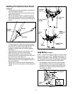
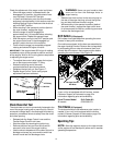
• Raise the upper handle assembly until it locks over
the lower handle. See Figure 4.
• Observe the lower rear area of the snow thrower to
be sure both cables are aligned with roller guides.
• Secure the upper handle and lower handle with the
two plastic wing knobs, cupped washers and
carriage bolt (eyebolt on the left side) previously
removed. See Figure 4.
Figure 4
• Adjust the eyebolt on the chute directional control
so the rod does not come into contact with the
engine by moving the hex nut against the handle (if
necessary). Retighten the wing nut to secure the
directional control in this position.
• Slide the connector down over the end of the lower
shift rod. See Figure 4. Tap the connector until it
locks on the lower shift rod.
If the connector is not properly assembled, the shift rod
will pivot and you will not be able to change speeds or
change directions.
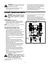
• Insert “Z” fitting (Hardware A) into hole in clutch
grips. See Figure 11. Two extra jam nuts are
included in the hardware pack in the event either
are lost during shipping.
• Thread the jam nuts all the way up each of the “Z”
fittings, toward the handle panel. See Figure 11.
• Make certain all cables are in the grooves of the
cable roller guides located in the lower rear of the
unit, one on each side. See Figure 9.
• Thread the coupling end of the cable onto the
threaded portion of the “Z” fitting until the rubber
bumper (located on the underside of the clutch
lever) only lightly contacts the upper handle.
IMPORTANT:
The cable should have very little slack, but
should NOT be tight. An overtightened cable may
prohibit the auger and drive from disengaging.
WARNING: Over-tightening the cable may
prohibit the auger and drive from disengaging
and compromise the safety of the snow
thrower. Do NOT overtighten the cable.
• Once properly adjusted, tighten the jam nut against
the coupling end of the cable to lock it in position.
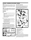
Refer to Auger Control Test on page 13 prior to operating
your snow thrower. Read and follow all instructions
carefully and perform all adjustments to verify your
snow thrower is operating safely and properly.
Assembly (Boxed Unit)
WARNING: Disconnect the spark plug
wire and ground it against the engine to
prevent unintended starting.
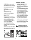
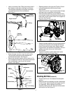
Attaching Handle Assembly
(Hardware Group A, B and E)
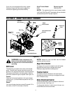
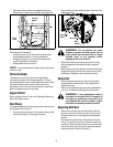
• Attach left handle and left clutch bracket to handle
panel with two carriage bolts, cupped washers and
hex patch nuts. (Be sure the bend in the grip
bracket is towards the center of the handle panel.)
Do not tighten at this time. See Figure 5.
Figure 5
Wing Knobs,
Washers
and Bolts
Eyebolt
Eyebolt
Wing Knobs
Connector
Hex
Nut
Hairpin Clip
Handle Panel
Carriage
Bolts
Left Bracket
Bell Washers
Left Handle
Hex
Patch Nuts
(Curves in)