


15
BRAKE ADJUSTMENT
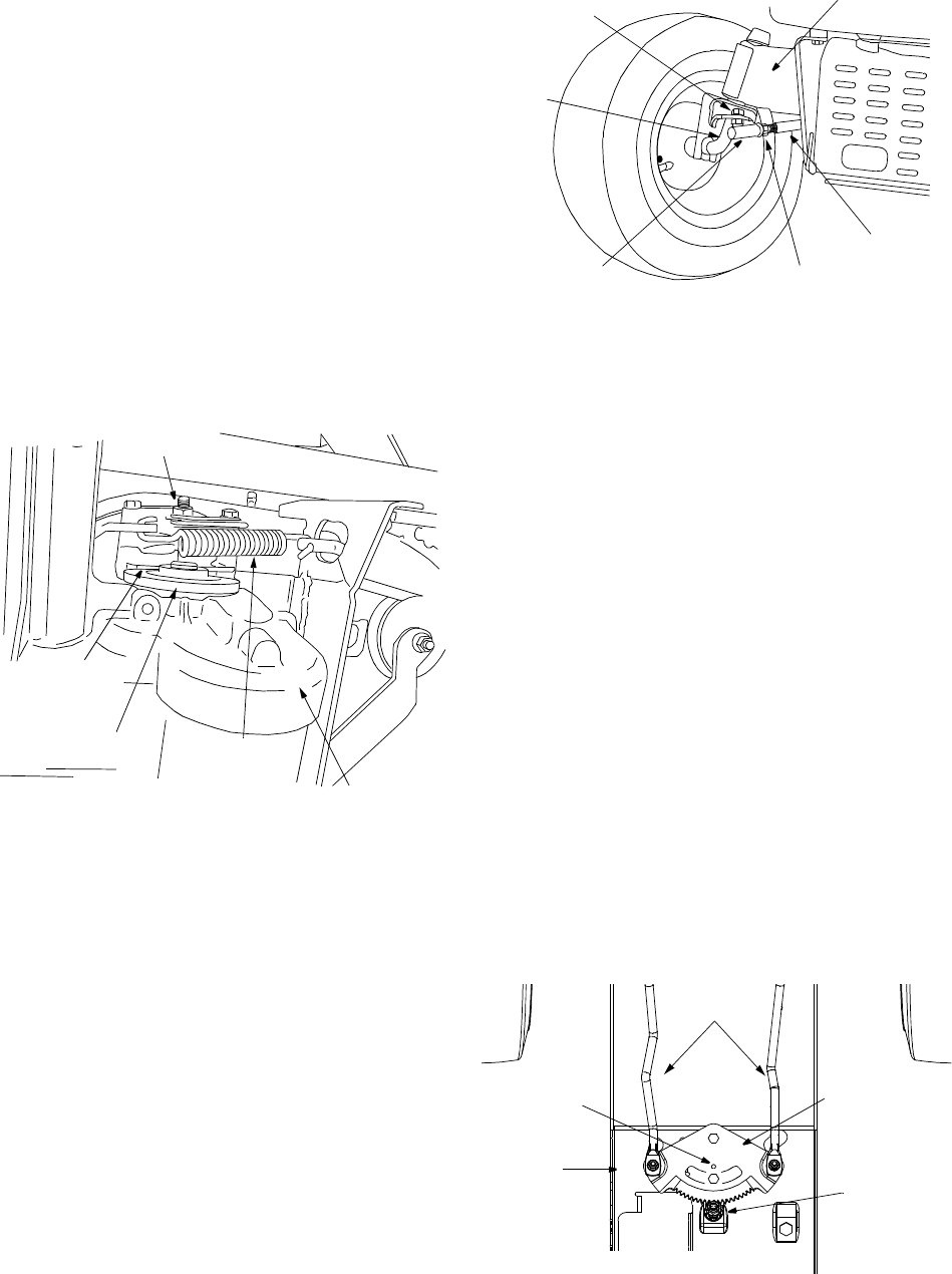
If the tractor does not come to a complete stop when
the brake pedal is completely depressed, or if the
tractor’s rear wheels can roll with the parking brake
applied, the brake is in need of adjustment. The
brake disc can be found on the right side of the
transmission in the rear of the tractor. Adjust if
necessary as follows:
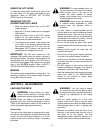
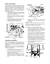
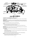
• Looking at the transmission from the right side
of the tractor, locate the compression spring
and brake disc. See Figure 9.
• Loosen, but do NOT remove, the hex nut
found on the right side of the brake assembly.
See Figure 9.
• Using a feeler gauge, set the gap between the
brake disc and the brake puck at .011".
• Re-tighten the hex nut loosened earlier.
Figure 9
STEERING ADJUSTMENT
If the tractor turns tighter in one direction than the
other, or if the ball joints are being replaced due to
damage or wear, the steering drag links may need to
be adjusted.
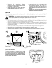
Adjust the drag links so that equal lengths are
threaded into the ball joint on the left side and the
ball joint on the right side:
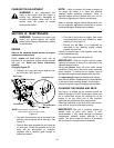
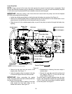
• Loosen the jam nut found on the drag link at
the rear of the ball joint. See Figure 10.
• Remove the hex nut and lock washer on the
top of ball joint. See Figure 10.
• Thread the ball joint toward the jam nut to
shorten the drag link. Thread the ball joint
away from the jam nut to lengthen the drag
link.
Figure 10
• Replace hex nut and lock washer and
retighten the jam nut after proper adjustment
is achieved.
NOTE: Threading the ball joints too far onto the
drag links will cause the front tires to "toe-in" too far.
Proper toe-in is between 1/16" and 5/16".
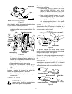
Front tire toe-in can be measured as follows:
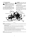
• Place the steering wheel in position for
straight ahead travel. Insert a 1/4" dowel up
through aligning holes in both the steering
gear and support plate. See Figure 11.
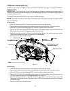
• In front of the axle, measure the distance
horizontally from the inside of the left rim to
the inside of the right rim. Note the distance.
• Behind the axle, measure the distance
horizontally from the inside of the left rim to
the inside of the right rim. Note the distance.
• The measurement taken in front of the axle
should be between 1/16" and 5/16" less than
the measurement taken behind the axle.
• Adjust if necessary.
• Remove the dowel inserted earlier before
attempting to operate the tractor.
Figure 11
Brake Disc
Hex Nut
Compression
Spring
Set Gap
at .011"
NOTE: View shown from beneath tractor.
Transmission
Drag Link
Ball Joint
Axle
Pivot BarHex Nut and
Jam Nut
Lock Washer
Steering Gear
Insert Dowel
Here
Drag Links
Steering
Shaft
Support
Plate
NOTE: View shown from beneath tractor.