


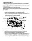
14
• Determine the approximate distance
necessary for proper adjustment and proceed,
if necessary, to the next step.
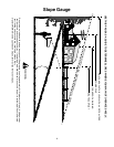
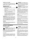
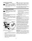
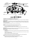
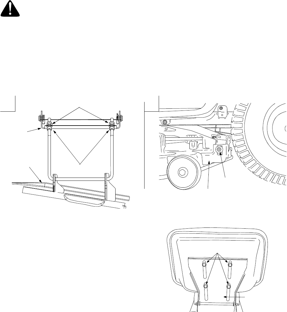
• Loosen the two jam nuts on the rear side of
the deck stabilizer bracket. See Figure 7A.
• Locate the two lock nuts on the opposite side
of the stabilizer bracket. See Figure 7A.
Tighten the lock nuts to raise the front of the
deck; loosen the lock nuts to lower the front of
the deck.
• Retighten the two jam nuts loosened earlier
when proper adjustment is achieved.
Side to Side
If the cutting deck appears to be mowing unevenly, a side-to-side adjustment can be performed. Adjust if
necessary as follows:
WARNING: Turn the tractor’s engine off, remove the key from the ignition switch and apply the
tractor’s parking brake before making any adjustments to the cutting deck.
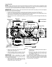
• With the tractor parked on a firm, level surface, place the lift lever in the top notch (highest position) and
rotate the both blades so that they are perpendicular with the tractor.
• Measure the distance from the outside of the left blade tip to the ground and the distance from the
outside of the right blade tip to the ground. Both measurements taken should be equal. If they’re not,
proceed to the next step.
• Loosen, but do NOT remove, the hex cap screw on the left deck hanger bracket. See Figure 7B.
• Balance the deck so that both blade tip measurements taken earlier are equal.
• Retighten the hex cap screw on the left deck hanger bracket when proper adjustment is achieved.
Figure 7
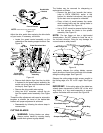
SEAT ADJUSTMENT
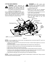
To adjust the position of the seat, loosen, but do
NOT remove the four screws which secure the seat
to the seat pivot bracket. Slide the seat forward or
backward until desired position is reached. Retighten
the four screws. See Figure 8.
Figure 8
Jam
Deck
Stabilizer
Bracket
Nuts
Lock
Nuts
Deck
Hex Cap Screw
Deck Hanger Bracket
A
B
F
ront to Rear
Side to Side
Screws
Seat Pivot
Bracket