


6
3
Setup and
Adjustment
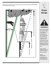
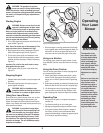
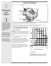
Stand behind the
mower as if you were
going to operate it.
Your right hand cor-
responds to the right
side of the mower; your
left hand corresponds
to the left side of the
mower.
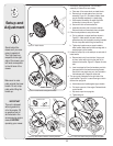
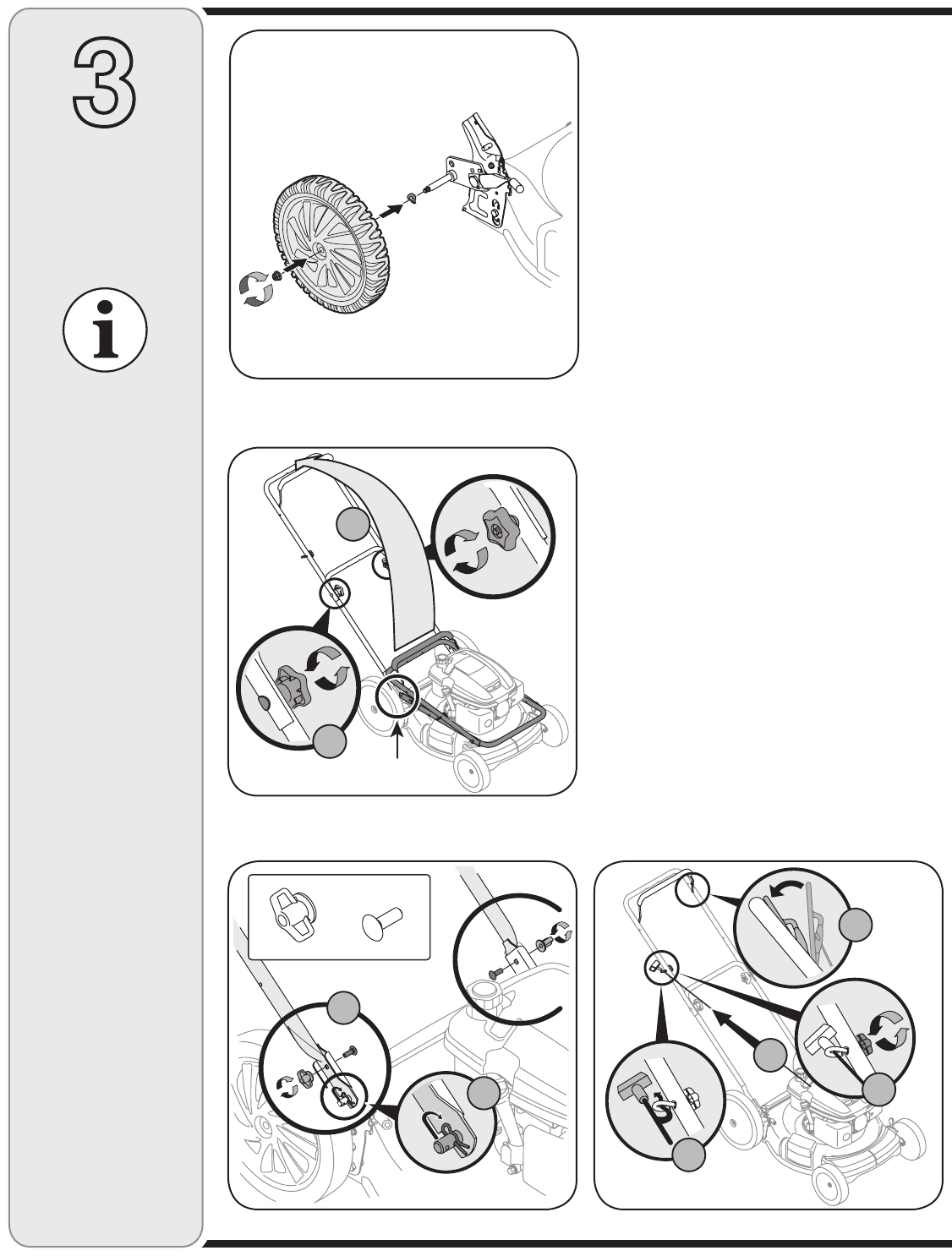
Figure 3-2: Unfold handle and tighten hardware.
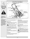
IMPORTANT
This unit is shipped
without gasoline or
oil in the engine. Fill
up gasoline and oil
as instructed in the
accompanying engine
manual BEFORE
operating your mower.
Make sure to route
cable outside the lower
handle. Do not crimp
cable while lifting the
handle up.
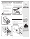
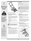
Figure 3-3: Secure lower handle to mounting brackets.
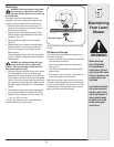
Figure 3-4: Pull recoil starter through rope guide and tighten.
Handle Bracket
B
A
Wing Nuts (2)
Hardware Pack
Carriage Bolts (2)
A
B
C
D
A
B
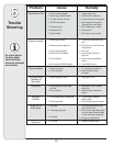
1. Remove any packing material. The first step in
assembly is to attach the rear wheels.
a. Place rear of the mower deck on raised blocks.
b. Remove lock nut and washer from pivot arm
assembly, Figure 3-1. (On select models, these
may be included separately in a plastic bag).
c. Slide washer followed by the wheel (both with
hollow side in) onto pivot arm, Figure 3-1.
d. Secure with lock nut removed earlier.
e. Assemble the other side in the same manner.
Remove blocks and lower deck when complete.
2. Follow the steps below to setup the handle.
a. Pull up and back on upper handle as shown in
Figure 3-2. Make certain the lower handle is
seated securely into the handle mounting brackets.
Do not crimp cable while lifting the handle up.
b. Tighten star knobs to secure upper handle to
lower handle. Make sure that each carriage bolt is
seated properly in the handle.
3. Locate the hairpin clip on the weld pin on each side of
lower handle.
a. Remove hairpin clip from this hole. Using a pair
of pliers, insert hairpin clip into the hole on pin
closest to the bracket, Figure 3-3. Repeat on other
side.
b. Insert a carriage bolt from the hardware pack into
the upper hole on the handle mounting bracket.
Secure with one plastic wing nut, also included in
the hardware pack. Repeat on other side.
4. The rope guide is attached to the right side of the
upper handle, Figure 3-4. Loosen the wing nut which
secures the rope guide.
a. Hold blade control handle against upper handle.
b. Pull starter rope out of the engine. Release blade
control handle.
c. Slip starter rope into rope guide.
d. Tighten wing nut.
Figure 3-1: Attach wheels.