6
SECTION 3: KNOW YOUR EDGER
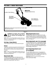
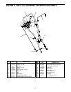
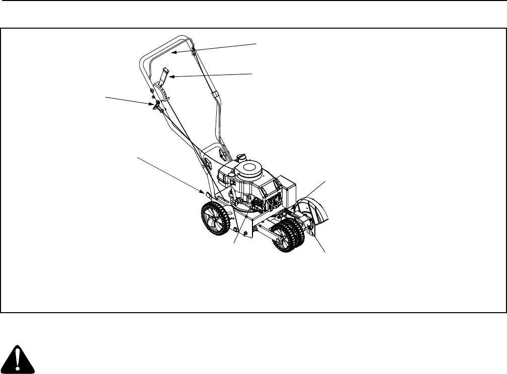
Figure 4
WARNING: Be familiar with all controls
and their proper operation. Know how to
stop the machine and disengage them
quickly.
NOTE: Refer to the Engine Manual packed with your
edger for a detailed description of all engine-related
controls and components.
Pull Rope / Recoil Starter
The pull rope/recoil starter is used to start the engine.
Primer
The primer is used to pump gas into the carburetor and
aid in starting the engine. Use it to start a cold engine,
but do not use it to restart a warm engine after a short
shutdown.
NOTE: Refer to the Engine Manual packed with your
edger for a detailed description of all engine-related
controls and components.
Blade Control Bail
Located on the upper handle, the blade control bail
must be depressed against the upper handle in order to
operate the unit. Releasing the blade control stops the
engine and the edger blade. See Figure 4.
Blade Depth Control Lever
The blade depth control lever is located on the right
side of the upper handle. It is used to control the depth
of the cut. The further forward the blade depth control
lever is moved, the deeper into the soil the edger blade
will cut. See Figure 4.
Bevel Adjustment Lever (if so equipped)
The bevel adjustment lever, if so equipped, is located
on the front, left portion of the edger, behind the edger
blade. It is used to vary the angle of the edger blade
between one of three positions for edging/trenching or
beveled edging. See Figure 4.
Curb Height Adjustment Lever
(if so equipped)
The curb height adjustment lever, if so equipped, is
found on the rear portion of the edger.When placed in
an applicable notch, it aids in stabilizing the edger while
edging grass along a curb. See Figure 4.
IMPORTANT:
Become familiar with all the controls
before operating the edger.
Pull Rope / Recoil Starter
Blade Depth
Control Lever
Curb Height
Adjustment Lever
NOTE:
Wheel and blade styles vary by model. Yours may differ slightly.
Blade Control Bail
Primer
Bevel Adjustment
Lever
Model 550 and 551 Shown.
(Transport Position Shown)
Spindle Sheaves Belt Guard
(If Equipped)
(If Equipped)


