


11
Replacing the Edger Blade
WARNING: The edger blade is sharp. Wear
leather work gloves to protect your hands
when working around the edger blade.
WARNING: Disconnect the spark plug wire
and ground against engine before
performing the following steps.
• Working in front of the edger, loosen the flange lock
nut on top of frame, allowing the idler pulley
assembly to pivot slightly out from the frame. See
Figure 16.
• With your other hand, carefully reach under the rear
of the unit and remove the belt from around the
engine flywheel pulley.
• Remove the spindle sheaves belt guard by
removing the two self-tapping screws which secure
it to the blade plate assembly. See Figure 11.
• Use two wrenches (one wrench to prevent the hex
bolt head from spinning and the other to remove the
hex lock nut and bell washer) to remove the edger
blade. Refer to Figure 12.
• Remove and discard the edger blade but retain the
bell washer and hex lock nut.
• Install the replacement edger blade, the bell
washer (cupped side facing inward) and the hex
lock nut removed earlier.
IMPORTANT:
Use a torque wrench to tighten the hex
lock nut to between 37 foot-lbs. and 50 foot-lbs.
• Reinstall the spindle belt guard with the self tapping
screws removed earlier.
• Carefully place the drive belt back onto the engine
flywheel pulley, and retighten the flange lock nut on
the top of the frame.
IMPORTANT:
Make certain that the drive belt is seated
correctly on the blade spindle and that it is riding
smoothly on the spindle sheaves and is not pinched
between them. Repeat the first three steps if the belt is
pinched.
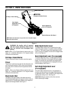
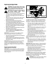
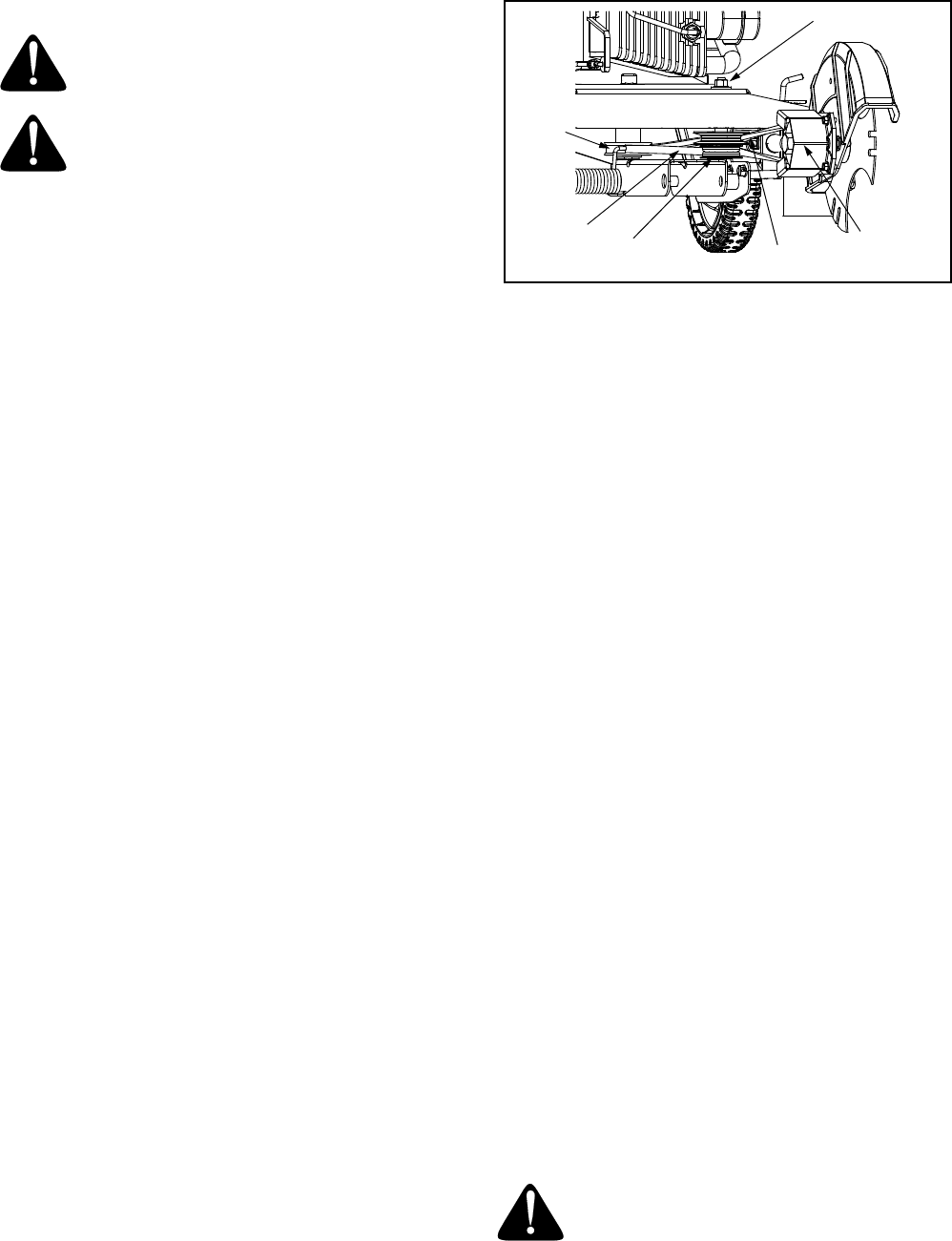
Replacing the Drive Belt
IMPORTANT:
To aid in reassembly, note the orientation
of the drive belt on the two idler pulleys and the engine
flywheel pulley prior to performing the following steps.
Refer to Figure 16.
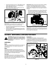
Figure 16
The edger drive belt is subject to wear and should be
replaced if any signs of cracking, shredding or rotting
are present. To replace the belt, proceed as follows:
• Working in front of the edger, loosen the flange lock
nut on top of frame, allowing the idler pulley
assembly to pivot slightly out from the frame. See
Figure 16.
• With your other hand, carefully reach under the rear
of the unit and remove the belt from around the
engine flywheel pulley.
• Remove the spindle sheaves belt guard by
removing the two self-tapping screws which secure
it to the blade plate assembly. See Figure 11.
• Carefully remove the belt from off of the pulleys,
again making sure to note the orientation of the
belt. Discard the belt.
Install the replacement belt (Part No. 754-04032) in the
same configuration that the original belt was routed as
follows:
• Working from the front of the edger, place the belt
onto the spindle sheaves, route it back onto the two
idler pulleys, and then place it onto the engine
flywheel pulley.
IMPORTANT:
Make certain that the “V” side of the belt is
seated into the top pulley and the flat side of the belt is
seated into the bottom pulley. See Figure 16.
• Reinstall the spindle sheaves belt guard with the
self tapping screws removed earlier.
• Make certain that the drive belt is on the engine
flywheel pulley and idler pulleys, and retighten the
flange lock nut on the top of the frame.
IMPORTANT:
Make certain that the drive belt is seated
correctly and that it is riding smoothly on the spindle
sheaves and is not pinched between them. Repeat the
first three steps if the belt is pinched.
WARNING: Never operate the edger without
the spindle sheaves belt guard in place.
Flat Side
of Belt
“V” Side
of Belt
Spindle Sheaves
Belt Guard
Flange Lock Nut
Idler Pulley
Assembly
Engine
Flywheel
Pulley