


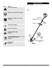
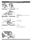

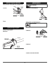

HOLDING THE TRIMMER
Before operating the unit, stand in the
operating position (Fig. 3). Check for the
following:
• The operator is wearing eye protection
and proper clothing
• With a slightly-bent right arm, the
operator’s right hand is holding the
shaft grip
• The operator’s left arm is straight, the
left hand holding the handle
• The unit is at waist level
• The cutting attachment is parallel to the ground and easily
contacts the grass without the need to bend over.
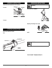
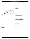
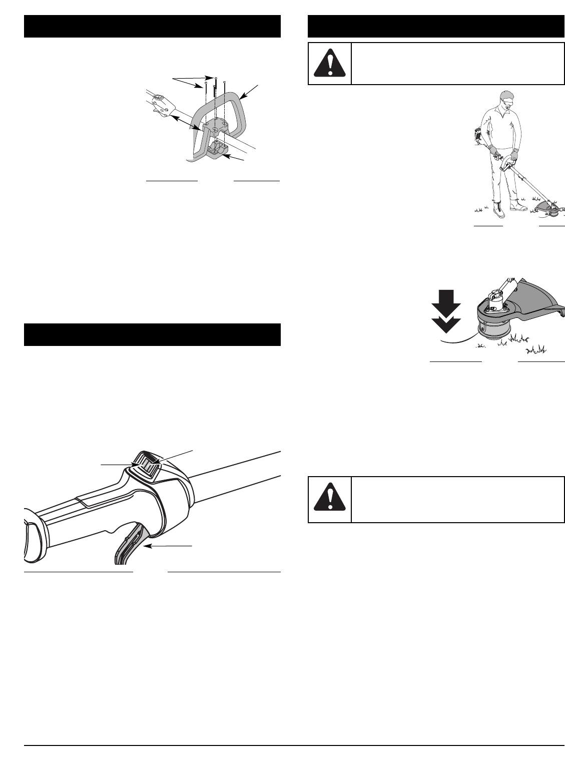
Adjusting Trimming Line Length
The Bump Head cutting
attachment allows you to
release trimming line without
stopping the engine. To
release more line, lightly tap
the cutting attachment on the
ground (Fig. 4) while
operating the trimmer at high
speed.
NOTE: Always keep the trimming line fully extended. Line
release becomes more difficult as cutting line becomes
shorter.
Each time the head is bumped, about 1 inch (25.4 mm) of
trimming line releases. A blade in the cutting attachment shield
will cut the line to the proper length if any excess line is released.
For best results, tap the bump knob on bare ground or hard
soil. If you attempt a line release in tall grass, the engine may
stall. Always keep the trimming line fully extended. Line release
becomes more difficult when the cutting line gets shorter.
NOTE: Do not rest the Bump Head on the ground while the
unit is running.
Some line breakage will occur from:
• Entanglement with foreign matter
• Normal line fatigue
• Attempting to cut thick, stalky weeds
• Forcing the line into objects such as walls or fence posts
TIPS FOR BEST TRIMMING RESULTS
• For best trimming results, operate unit at full throttle.
• Keep the cutting attachment parallel to the ground.
• Do not force the cutting attachment. Allow the tip of the line to
do the cutting, especially along walls. Cutting with more than the
tip will reduce cutting efficiency and may overload the engine.
• Cut grass over 8 inches (200 mm) by working from top to
bottom in small increments to avoid premature line wear or
engine drag.
Fig. 3
WARNING: Always wear eye, hearing, foot and
body protection to reduce the risk of injury when
operating this unit.
OPERATING INSTRUCTIONS
WARNING: Do not remove or alter the line cutting
blade assembly. Excessive line length will make
the clutch overheat. This may lead to serious
personal injury or damage to the unit.
Fig. 4
4
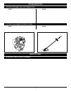
ASSEMBLY INSTRUCTIONS
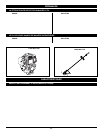
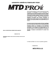
INSTALLING AND ADJUSTING THE D-HANDLE
If your unit has the D-Handle pre-installed, please follow the
“To Adjust” instructions only.
To Install
1. Remove the screws and
bottom clamp piece that
were installed on the D-
handle for shipping.
2. Place the D-handle over
the shaft housing and onto
the bottom clamp (Fig. 1).
Place it a minimum of 6 in
(15.24 cm) from the end of
the shaft grip.
3. Start screws with a large Flat-head or T-25 Torx
screwdriver. Do not tighten until you make the handle
adjustment.
To Adjust
4. If the D-handle was pre-installed, loosen the screws on the
handle just enough to move it.
5. While holding the unit in the operating position, manuever
the D-handle to the location that provides you the best grip
(Fig. 3).
6. Tighten the clamp screws evenly, until the D-handle is
secure.
(4) Screws
D-Handle
Bottom
Clamp
Fig. 1
Minimum
6 inches
(15.24 cm)
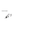
STOPPING INSTRUCTIONS
Note: This unit has a Momentary Switch. The On/Off Contol
Switch will be in the On position at all times.
1. Release your hand from the throttle control. Allow the
engine to cool down by idling.
2. Press the On/Off Stop Control in the OFF (O) position and
hold until the unit completely stops running. (Fig. 2)
STOPPING INSTRUCTIONS
Start/On ( I )
Stop/Off (O)
Throttle
Control
Fig. 2