


8 Section 3— ASSembly & Set-Up
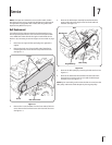
Handlebar Assembly
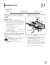
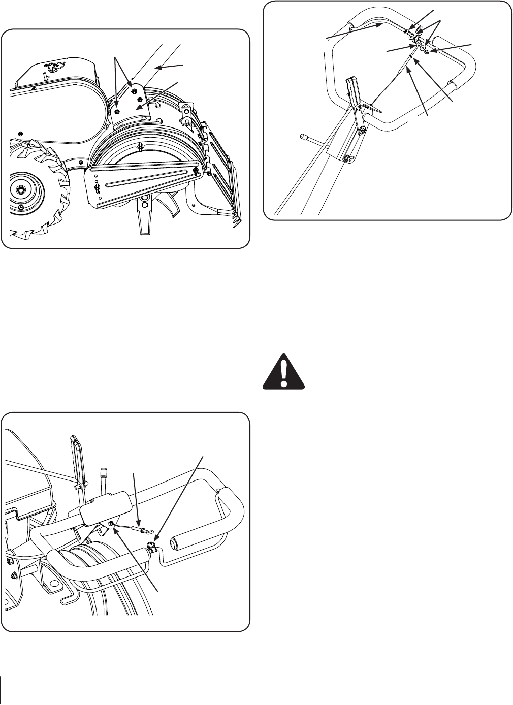
1. Remove the top two bolts and flange lock nuts from the
handle mounting brackets, but do not remove the bottom
bolt and nut. See Figure 3-2.
Bolts & Flange
Lock Nuts
Handle
Assembly
Handle
Bracket
Figure 3-2
2. Place the handle assembly in position between the handle
mounting brackets.
3. Line up the holes in the handle with the holes in the
bracket and secure with the hardware previously removed.
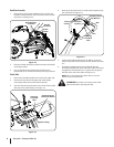
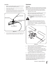
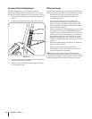
Clutch Cable
1. Remove the threaded eyebolt and nut from the cable end.
2. Route the clutch cable to the right side of the handle
mounting brackets and underneath the handle.
3. Push the cable through the hole in the center of the handle
and snap in the plastic fitting. See Figure 3-3.
Internally
Threaded
Tube
Slot Head Screw,
Nut & Flat Washer
Plastic Fitting
Figure 3-3
4. Remove the slot head screw, nut and two flat washers from
the clutch bail. See Figure 3-4.
Slot Head Screw
Flat Washers
Nut
Nut
Internally
Threaded
Tube
Threaded
Eyebolt
Clutch
Control
Figure 3-4
5. Fasten the threaded eyebolt onto the bail by securing it
from the top with the slot head screw, flat washers and lock
nut.
6. Thread the eyebolt and nut removed earlier into the
internally threaded tube at the end of the cable. The thread
engagement should be about ⁄”. Tighten the nut against
the tube at the end of the cable. See Figure 3-4.
NOTE: Do not overtighten the clutch cable. Too much
tension may cause it to break.
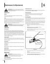
WARNING! Be certain to check the clutch cable
adjustment before operating the tiller.