


5
SECTION 2: ASSEMBLING YOUR TILLER
NOTE: This operator’s manual covers various models
of tillers. The units illustrated may vary slightly from
your unit. Follow only those instructions which pertain
to your model number.
NOTE: References to right or left side of the tiller are
determined from behind the unit in the operating
position.
To Remove Unit From Carton
• Remove staples, break glue on top flaps, or cut
tape at carton end and peel along top flap to open
carton.
• Remove loose parts included with unit (i.e.,
operator’s manual, etc.).
• Cut corners and lay carton down flat.
• Remove packing material.
• Roll or slide unit out of carton. Check carton
thoroughly for loose parts.
• Extend control cable and lay on the floor. Be careful
not to bend or kink control cable.
IMPORTANT:
This unit is shipped without gasoline or oil
in the engine. Be certain to service engine with gasoline
and oil as instructed in the separate engine manual
before operating your machine.
Loose Parts In Carton
Depth Stake
Handle Assembly
Shift Rod
NOTE: All hardware needed for assembly is attached
to the loose parts or the tiller.
Before Assembly
WARNING: Disconnect the spark plug wire
and ground it against the engine to prevent
unintended starting.
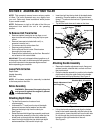
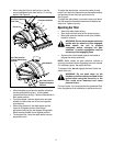
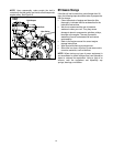
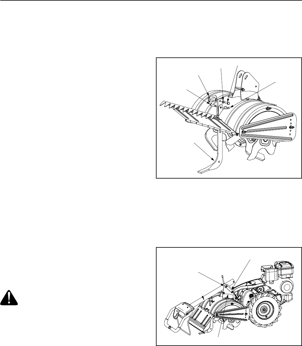
Attaching Depth Stake
• Tip the tiller forward so it rests on front
counterweight.
• Unthread the “T” knob from the top of the depth
stake and remove the flat washer and hex bolt.
Remove the hairpin clip from the clevis pin.
See Figure 1.
• Raise the tine shield hinge flap assembly and insert
the depth stake assembly in the slot (under the tine
shield) and up through the tine shield assembly.
• Insert clevis pin through the tine shield and depth
stake assemblies. Secure with hairpin clip.
• Insert hex bolt into the top hole of the depth stake
assembly. Place flat washer on the hex bolt and
thread “T” knob onto the hex bolt. Tighten securely.
See Figure 1.
• Tip the tiller back down so it rests on the tines.
Figure 1
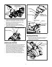
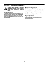
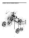
Attaching Handle Assembly
• Remove the handle adjustment crank, flange nut,
retainer bracket, shoulder bolt, and lock nut from
the pivot bracket.
• Place the handle assembly in position in the handle
pivot bracket lining the upper holes in the handle
with the slots in the pivot bracket. See Figure 2.
Figure 2
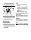
• Lift up the handle assembly and align the bottom
holes in the handle assembly with the holes in the
pivot bracket. Insert shoulder bolt from the left side
of unit through the pivot bracket and the retainer
bracket on the right hand side of the unit.
See Figure 3.
T-Knob
Flat Washer
Hex Bolt
Hairpin Clip
Clevis Pin
Depth Stake
Pivot Bracket
Handle Adjustment Crank
and Flange Nut
Retainer Bracket,
Shoulder Bolt, & Lock Nut