


5
SECTION 2: ASSEMBLING YOUR TILLER
NOTE: This operator’s manual covers various models
of tillers. The units illustrated may vary slightly from
your unit. Follow only those instructions which pertain
to your model number.
NOTE: References to right or left side of the tiller are
determined from behind the unit in the operating
position.
To Remove Unit From Carton
• Remove staples, break glue on top flaps, or cut
tape at carton end and peel along top flap to open
carton.
• Remove loose parts included with unit (i.e.,
operator’s manual, etc.).
• Cut corners and lay carton down flat.
• Remove packing material.
• Roll or slide unit out of carton. Check carton
thoroughly for loose parts.
• Extend control cable and lay on the floor. Be careful
not to bend or kink control cable.
IMPORTANT:
This unit is shipped without gasoline or oil
in the engine. Be certain to service engine with gasoline
and oil as instructed in the separate engine manual
before operating your machine.
Loose Parts In Carton
Tailpiece and Depth Stake
NOTE: All hardware needed for assembly is attached
to the loose parts or the tiller.
Before Assembly
WARNING: Disconnect the spark plug
wire and ground it against the engine to
prevent unintended starting.
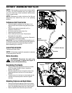
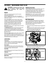
Assembling The Handle
• Remove the handle adjustment lever from handle
and lift up upper handle to raise in operating
position. See Figure 1.
• Reinsert adjustment lever through the lower hole,
tightening the lever into lock nut on the retainer
bracket.
• Once the lever is in the lock nut, the handle can be
moved to the desired position and then tighten
securely.
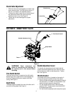
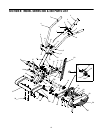
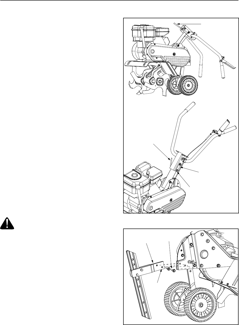
Attaching Tailpiece and Depth Stake
• Remove the two self-tapping screws on the frame
and slide the tailpiece into the frame, with the lower
hole in the tailpiece toward the front. See Figure 2.
• Secure tailpiece with the screws just removed.
Figure 1
Figure 2
Handle
Adjustment Lever
Handle
Adjustment Lever
Retainer Bracket
Lock Nut
Tailpiece
Self-Tapping
Screws
Lower Hole