


8
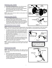
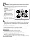
Attaching “Z” Fitting
3. Hold the cable end near the left side of the upper handle
and hook the “Z” end of the brake cable into the blade
control handle from the inside to outside. See Figure 7A.
Securing Brake Cable
4. Secure the cable to the lower left handle near the base of
the unit with a cable tie from group 3 of the hardware pack.
Trim off extra length of the cable tie. See Figure 7B.
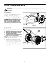
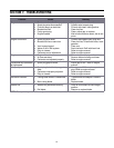
Attaching Wheels
1. Block the mower securely.
2. Place the larger two wheels on the rear pivot arm axles
and secure with the lock nuts from group 4 of the hardware
pack.See Figure 8.
3. Repeat with the two smaller wheels on the front pivot arm
axles.
4. Remove blocks and put the mower on ground.
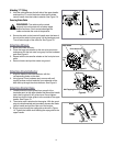
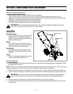
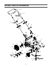
Attaching Chute Deflector
1. Align the holes on the chute deflector with the
corresponding holes on the deck.
2. Using group 5 from hardware pack, secure with self
tapping screws and bell washers from underside of the
deck and up through the chute deflector. See Figure 9.
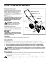
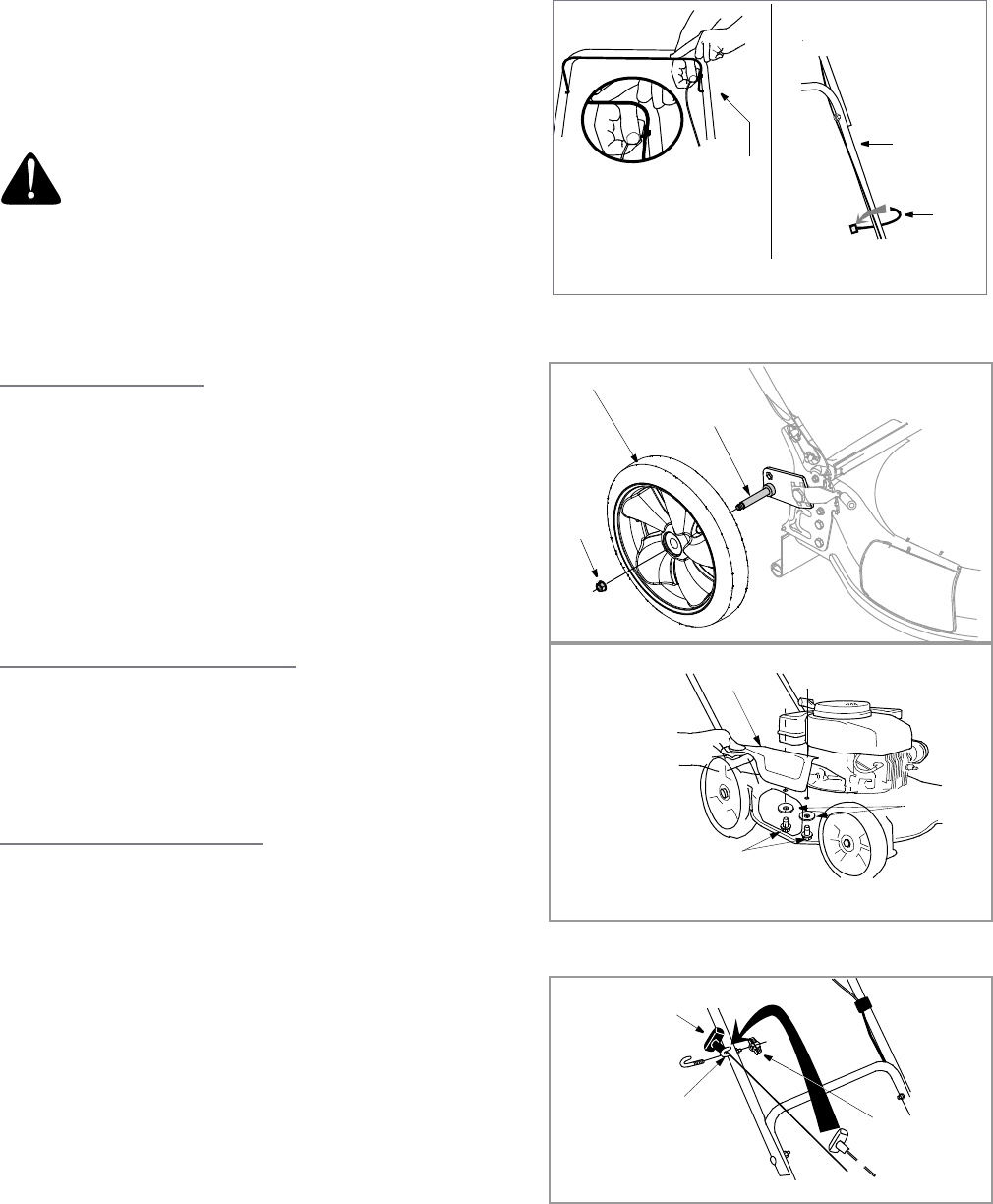
Attaching Starter Rope
1. Loosely attach the rope guide (from group 6 of the
hardware pack) to the upper handle and thread the handle
knob (also in group 6) only a few turns. Do not tighten.
Make sure that the rope guide is to the outside of the upper
handle. See Figure 10.
2. The starter rope is attached to the engine. With the spark
plug wire disconnected and grounded, depress the blade
control handle and pull the rope out of the engine.
3. Slip the rope through the rope guide as shown in Figure
10. Tighten the handle knob holding the rope guide to the
upper handle.
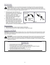
WARNING: The cable must be routed
properly to avoid contact with all sharp edges
and hot surfaces. Such contacts damage the
cable and render the controls inoperative.
Figure 7
Lower
Cable
Handle
Tie
Z Fitting
AB
Figure 8
Lock
Pivot Arm Axle
Rear Wheel
Nut
Chute
Deflector
Bell
Self Tapping Screws
Figure 9
Washers
Rope
Guide
Starter
Rope
Handle
Figure 10
Knob