


7
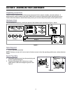
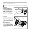
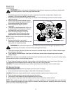
Attaching Lower Handle
1. Lift the rear of the deck and place it on a block securely.
2. Place the lower handle over the handle bracket
assemblies and position each handle bracket assembly
stud into the bottom hole in the lower handle.
3. Secure with the wing nuts from group 1 of the hardware
pack. See Figure 3.
NOTE: Each end of the lower handle must be placed in the
same relative position.
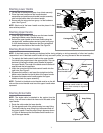
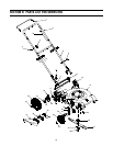
Attaching Upper Handle
1. Place the upper handle in position over the lower handle
keeping the blade control handle facing up.
2. Secure the upper handle to the lower handle using the
carriage bolts, saddle washers and wing nuts from group
2 of the hardware pack. Make sure that the carriage bolt
heads go on the outside of the handle. See Figure 4.
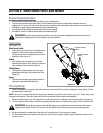
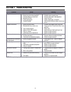
Attaching Blade Control Handle
NOTE: If the blade control handle got displaced either during shipping or during assembly of other two handles,
reassemble it now. If the blade control handle is firmly secured in place, you may proceed to the next assembly.
1. To reattach the blade control handle to the upper handle,
first identify the proper holes in the upper handle. This can
be done by placing the blade control handle flat against
the upper handle. The ends of the blade control handle will
approximate the hole positions.
2. Insert the curved end of the blade control handle into the
right hole. See Figure 5.
3. Squeeze the handle in, and insert the straight end of the
blade control handle into the left hole of the upper handle.
4. Squeeze the blade control handle against the upper
handle to check for proper assembly.
NOTE: The hole in the blade control handle must be on the left
side and the control handle must touch the upper handle when
squeezed.
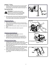
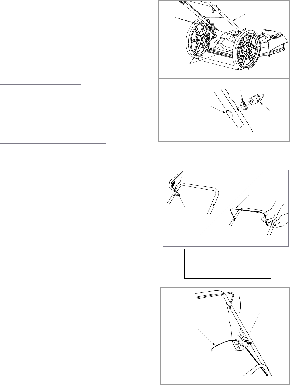
Attaching Brake Cable
NOTE: The brake cable is attached to the engine from the
factory. You will have to attach the free end of the cable to the
upper handle.
1. Route the cable under the lower handle.
2. On the opposite end of the cable housing is a snap fitting.
The shaft inside the snap fitting fits in the second hole on
the upper handle. Press the snap fitting in place as shown
in Figure 6. Make sure that the blade control handle is on
top of the upper handle.
Figure 3
Lower
Handle
Wing
Nuts
Handle
Bracket
Assemblies
Figure 4
Saddle
Washer
Wing Nut
Carriage Bolt
Blade Control
Handle
Insert one end of
handle herecontrol
Figure 5
IMPORTANT
The blade control handle is a safety
device. Never attempt to bypass its
operations.
Snap Fitting
Brake Cable
Figure 6