


11
ENGLISH
EN
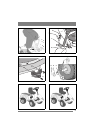
The seat can be folded. If the machine is parked
outside when it is raining, fold the seat forward to
protect the seat cushion from getting wet.
The seat is locked. To fold the seat up or down, re-
lease the catch (S).
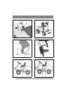
4.5 Steering wheel
See fig. 7. In order to minimise the axial play in the
steering column, the shim washers (D) and/or (E)
must be installed on the steering column between
the steering column jacket and the bracket as fol-
lows.
1. Install the steering column jacket on the steer-
ing column and secure by knocking in the ten-
sion pin (C) approximately 1/3 of its length.
2. Pull the steering column jacket and the steering
column up.
3. From the outside, check whether no washers,
the 0.5 mm washer, the 1.0 mm washer or both
washers can be inserted into the gap. The wash-
er/washers must not be forced in, as there must
be a little axial play.
4. Pull out the cotter pin and dismantle the steering
wheel jacket.
5. Install the washer/washers in accordance with
point 3 above.
6. Install the steering column jacket on the steer-
ing column and secure by knocking in the ten-
sion pin fully. Use a counterhold.
4.6 Towing hitch
See fig. 8. Screw the towing hitch (J) into the two
holes on the underside of the rear axle using screws
(L+K). Tighten the screws properly.
Tightening torque: 22 Nm.
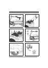
4.7 Deck mounts
This only describes installation on the right-hand
axle. Same procedure must be carried out on the
left-hand axle.
1. Lubricate the axle ends and the deck mount’s
bearing surface with oil before installation.
2. Install the deck mounts to the machine accord-
ing to fig. 9.
3. Install the locking pin (9:Q) in the hole in the
axle.
4.8 Tyre pressure
Check the air pressure in the tyres. Correct air
pressure:
Front: 0.6 bar (9 psi)
Rear: 0.4 bar (6 psi)
4.9 Accessories
For the installation of accessories, see separate in-
stallation guide supplied with each accessory.
Note: The cutting deck is regarded as an accessory
here.
5 DESCRIPTION
5.1 Transmission
5.1.1 HST
The machine is rear wheel drive.
The rear axle is equipped with a hydrostatic trans-
mission with infinitely variable forward and re-
verse gear ratios.
The rear axle is also equipped with a differential to
facilitate turning.
Front mounted tools are driven by drive belts.
5.1.2 4WD
The machine has 4-wheel drive. The power from
the engine to the drive wheels is transferred hy-
draulically. The engine drives an oil pump, which
pumps oil through the rear and front axle drives.
The front axle and rear axle are connected in se-
ries, which means that the front wheels and rear
wheels are forced to rotate at the same speed.
To make turning easier, both axles are equipped
with differential.
Front-mounted implements are powered via drive
belts.
5.2 Steering
The machine is articulated. This means that the
chassis is divided into a front and a rear section,
which can be turned in relation to each other.
The articulated steering means that the machine
can turn around trees and other obstacles with an
extremely small turning radius.
5.3 Safety system
The machine is equipped with an electrical safety
system. The safety system interrupts certain activ-
ities that can entail a danger of incorrect manoeu-
vres. For example, the engine cannot be started if
the clutch-parking brake pedal is depressed.
The operation of the safety system must
always be checked every time before
use.
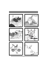
5.4 Controls
5.4.1 Implement lifter, mechanical (12:A)
To switch between working position and transport
position:
1. Depress the pedal fully.
2. Release the pedal slowly.