


OM-499 Page 14
Return To Table Of Contents
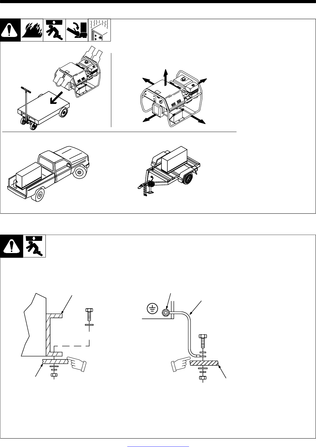
SECTION 5 − INSTALLATION
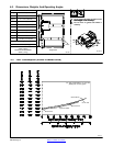
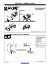
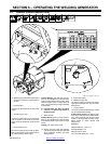
5-1. Installing Welding Generator
install1 10/00*− 802 524-A / Ref. 151 556 / 158 936-A / S-0854
18 in
(460 mm)
18 in
(460 mm)
18 in
(460 mm)
18 in
(460 mm)
18 in
(460 mm)
OR
Movement Airflow Clearance
Location
Y Always securely fasten welding
generator onto transport vehicle
or trailer and comply with all DOT
and other applicable codes.
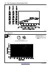
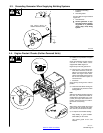
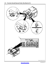
5-2. Grounding Generator To Truck Or Trailer Frame
install1 10/00* − Ref. 151 556 / S-0854
Y Always ground generator
frame to vehicle frame to pre-
vent electric shock and static
electricity hazards.
1 Generator Base
2 Metal Vehicle Frame
3 Equipment Grounding
Terminal
4 Grounding Cable
Use #10 AWG or larger insulated
copper wire.
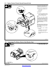
Y If unit does not have GFCI re-
ceptacles, use GFCI-
protected extension cord.
1
2
Electrically bond generator frame to
vehicle frame by metal-to-metal con-
tact.
GND/PE
3
4
2
OR