


66
APPENDIX G:
14" LX200GPS FEATURES
14" LX200GPS Unique Features
The 14" LX200GPS contains, for the most part, the same features (covered earlier in
this manual) as all other LX200GPS telescope models.
The following features are unique to the 14" model:
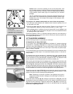
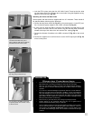
Battery Compartment
The battery compartments for the 14"
LX200GPS are located under the horizontal
beam of the fork arms (Fig. 55a). Each compartment has an indentation below it (Fig.
55b) to allow you to slide out the compartment easily.
Important Note: The compartments are designed to hold batteries only.
Do not use these compartments to store any other items.
Two button-head screws are provided to secure the battery compartments when using
the telescope in equatorial alignment. The telescope ships with the screws installed.
To install the batteries, first remove the screws with the supplied hex key. See Fig. 55c
for location of the screws. Next, remove the battery holder and install the batteries as
described in step #2 on page 13. Replace the holder and close the compartment.
Replace the screws if you plan to use the telescope in equatorial alignment. These
screws are not necessary when using the telescope in altazimuth alignment.
2" Diagonal Mirror with 1.25" Adapter
The 14"
LX200GPS comes equipped with a 2" diagonal mirror with a 1.25" adapter.
See pages 13 and 14 for information on how to install these devices to the microfo-
cuser assembly.
Optical Tube Assembly
Important Note: Attaching the 14" LX200GPS optical tube assembly to the
tripod is identical to the procedure described on pages 12 and 13.
Caution: Due to the weight and size of this product please use extreme
caution whenever assembling, disassembling, lifting, transporting or stor-
ing this product. Two or more persons should always be used whenever
performing any of the above tasks. Disregard for the above warning could
result in serious injury or death.
Caution: On the rear section of the optical tube is a red slot-head bolt,
used only for safety reasons in shipment. Remove this bolt before
attempting to turn the focus knob. In its place, insert the rubber plug pro-
vided as a dust protector (this rubber plug is included with your hardware
package).
The 14”
LX200GPS should never be commercially shipped without the red
bolt in place. This is essential during commercial transport, where rough
handling may occur. Your transport and storage of the telescope never
requires this bolt.
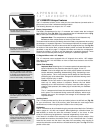
Auxiliary Jacks
The 14" model provides auxiliary focus and reticle jacks on the left fork arm (Fig. 56)
for your convenience. Use of the auxiliary jacks eliminates the cord tangle which
sometimes occurs when using the jacks located on the control panel
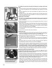
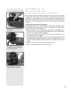
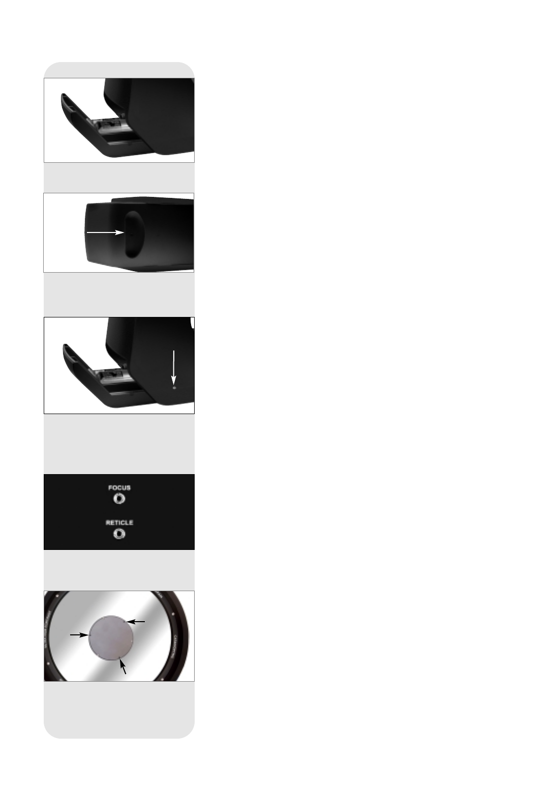
Collimation
The 14"
LX200GPS can be collimated using the procedure described in the Collimation
section, pages 44 - 46, with one exception: When tightening a collimation screw, it is
not necessary to loosen the other two collimation screws, or vice versa. In other
words, the screws may be tightened or loosened independently of each other.
A hex wrench is included in the accessory kit for collimation (use the smaller of the
two included hex wrenches; the smaller wrench is only included with the 14" model).
Insert the hex wrench into the slots in the plate of the secondary mirror housing to
access the collimation screws which are housed below the plate. See Fig. 57 for the
position of the slots.
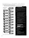
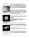
Fig. 55a: One of the two 14"
LX200GPS battery compartments.
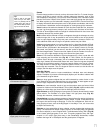
Fig. 57: Insert the included hex
wrench into the slots in the plate of
secondary mirror housing to access
the collimation screws (14" model
only).
Fig. 55b: An indentation on the
underside of one of the 14"
LX200GPS battery compartments.
Fig. 56: 14" model auxiliary focus
and reticle jacks are located on the
left fork arm.
Fig. 55c: Location of one of the bat-
tery compartment screws.The other
is located on the opposite end of the
horizontal beam of the fork arms
near the other battery compartment.