


INDEX
eyepiece fi eld of view (Fig. 8, 2), in the same
direction as the darker shadow is offset in the
ring of light.
4. Turn the set screw that you found with the
pointing exercise while looking in the eyepiece.
You will notice that the star image will move
across the fi eld. If while turning the defocused
star image fl ies out of the eyepiece fi eld, then
you are turning the screw the wrong way. Turn
the opposite direction and bring the image back
to the center of the fi eld.
5. If the screw you are turning becomes very loose,
tighten the other two screws by even amounts. If
the screw you are turning gets too tight, un-thread
the other two by even amounts.
6. When you bring the image to center (Fig.
8, 3), carefully examine the evenness of the ring
of light (concentricity). If you fi nd that the dark
center is still off in the same direction, continue to
make the adjustment in the original turning
direction. If it is now off in the opposite direction,
you have turned too far and you need to turn in
the opposite direction. Always double check the
image in the center of the fi eld of the eyepiece.
7. You may fi nd after your initial adjustment that the
dark center is off in a new direction (e.g., instead
of being off side-to-side it is now off in an up-and-
down direction). In this case
repeat steps 2
through 6
to fi nd the new adjustment screw.
8. Now try a higher power eyepiece (e.g., 9mm or
less) and repeat the above tests. Any lack of
collimation at this point will require only very
slight adjustments of the three set screws. You
now have good collimation of the optics.
9. As a fi nal check on alignment, examine the star
image in focus with the higher power eyepiece
as suggested above, under good viewing
conditions. The star point should appear as a
small central dot (commonly referred to as an
“Airy disc”) with a diffraction ring surrounding it.
To give a fi nal precision collimation, make
extremely slight adjustments of the three set
screws, if necessary, to center the Airy disc in the
diffraction ring. You now have the best alignment
of the optics possible with this telescope.
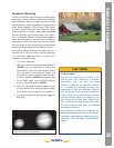
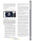
dark central spot is in fact the shadow of the secondary
mirror. Turn the focus knob until the ring of light fi lls
about 10% of the eyepiece fi eld-diameter. If the dark
central spot is offset in (i.e., not concentric with) the ring
of light, your telescope’s optical system is misaligned
and requires collimation.
Follow these steps for collimation of the
optical system:
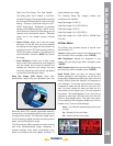
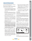
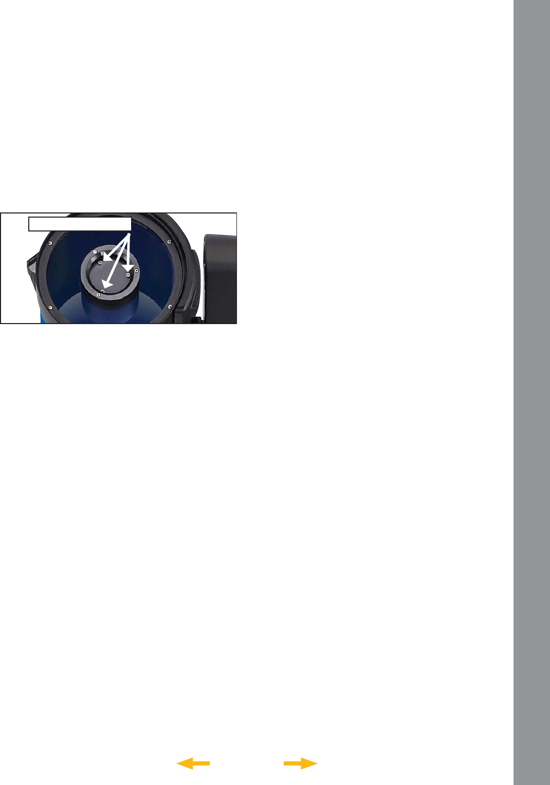
1. The only adjustments possible, or necessary, on
the LS are from the three inner most screws
located at the inner surface of the secondary
mirror housing.
CAUTION: Do not force the three collimation screws
past their normal travel and do not loosen them
more than two full turns in a counterclockwise
direction or the secondary mirror may come loose
from its support. You will fi nd that the adjustments
are very sensitive, usually requiring only one-half
turn or less to produce the desired result.
2. While looking at the defocused star image, notice
which direction the darker shadow is offset in
the ring of light or notice which part of the ring is
the thinnest (Pg. 32 Fig. 8, 1). Place your index
fi nger in front of the telescope so that it touches
one of the collimation set screws. You will see the
shadow of your fi nger in the ring of light. Move
your fi nger around the edge of the black plastic
secondary mirror support until you see the
shadow of the fi nger crossing the thinnest part
of the ring of light. At this point, look at the front of
the telescope where your fi nger is aiming. It will
either be pointing directly at a set screw, or it will
be between two set screws aiming at the set
screw on the far side of the black plastic
secondary mirror support. This is the set screw
that you will adjust.
3. Using the Arrow keys at the slowest slew speed,
move the defocused image to the edge of the
MAINTENANCE
Collimation Screws
34