


– 5 –
INTRODUCTION
This manual details the set-up, operation, specifications and optional accessories of the Polaris 60EQ-D 2.4"
(60mm) Equatorial Refracting Telescope.
STANDARD EQUIPMENT
• Complete optical tube assembly (objective lens diameter = 60mm; focal length = 900mm)
• Full-length, fully adjustable, aluminum tripod and accessory tray
• SR4mm (225x), H12.5mm (72x), and H25mm (36x) Eyepieces (.965" O.D. “Outside Diameter”)
• 3X Barlow lens (.965" O.D.)
• Diagonal mirror (.965" O.D.)
• 5x24mm viewfinder with bracket
• Complete equatorial mount with counterweight assembly
• Flexible control cables on both axes
• Hardware package: A. 3 bolts (3" long) with wing nuts and washers
B. 3 screws (1/2" long) with wing nuts and screwdriver tool
• StarFinder astronomy software (separate instructions supplied in software package)
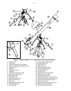
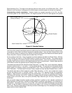
UNPACKING AND ASSEMBLY (Numbers in brackets below refer to Fig. 1)
1. Remove and identify the telescope’s components, using the listing above.
2. Attach the 3 aluminum tripod legs (2) to the base of the equatorial mount (4) with the 3 hinged leg braces
(3) facing inward. Three bolts (32) each about 3" long, with washers and wing nuts, are provided for this
purpose in hardware package “A.” Stand the telescope mount upright, spreading the tripod legs evenly
apart so the accessory tray can be positioned to attach to the 3 leg braces.
3. Attach the accessory tray (1) to the leg brace supports (3) with the 3 short screws and wing nuts
provided in hardware package “B.” Place the accessory tray on top of one of the leg braces (3) of the
tripod so that the mounting screw passes through the hole at one of the corners of the accessory tray
(1), and through the hole at the end of the leg brace (3). Then thread-on and tighten the wing nut.
Repeat this procedure until all 3 corners are mounted to the 3 leg braces.
4. Extend the sliding inner portion of the adjustable height tripod leg (30) to the desired length for all 3 legs.
Lock in place by tightening the leg lock thumbscrew (31) for each leg.
5. Holding the counterweight (18) firmly in one hand, slip the counterweight onto the counterweight shaft
(17). Attach the counterweight and counterweight shaft, by supporting the unlocked (20) counterweight
firmly in one hand while threading the counterweight shaft into the base of the Declination axis of the
telescope’s equatorial mount. Once firmly attached, slide the counterweight about 2 inches from the
bottom of the counterweight shaft and secure it in place with the locking thumbscrew (20) of the
counterweight. Note: if the counterweight ever slips, the secured threaded safety washer/screw (19)
will not let the weight slide entirely off the counterweight shaft. Be certain that this safety
washer/screw is always in place.
6. Attach the flexible cables (27) and (28), as shown. These cables are secured in place with a firm
tightening of the thumbscrews located at the attachment ends of each cable.
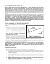
7. Tilt the polar axis (15) of the telescope to roughly a 45° angle with the horizon, as shown in Fig. 1. This
tilt is accomplished by first loosening the lock control at (24); this lock control, called the “Latitude
Adjustment Lock” is shown in Fig. 1 on top of page 4. With the polar axis thus tilted, firmly re-tighten
the latitude control lock.
8. Remove the wing nuts (34) from the optical tube mounting bolts (35) that are the underside of the main
optical tube (11) of the telescope. Then lay the telescope optical tube assembly onto the saddle plate
(10) passing the mounting bolts (35) through the holes in the saddle of the mount. Re-attach the wing
nuts (34) to the mounting bolts, and tighten to a firm feel. Be sure the focuser portion of the optical tube
is on the same side of the saddle as the slow-motion control cable in Declination (28), see Fig. 1.