


5
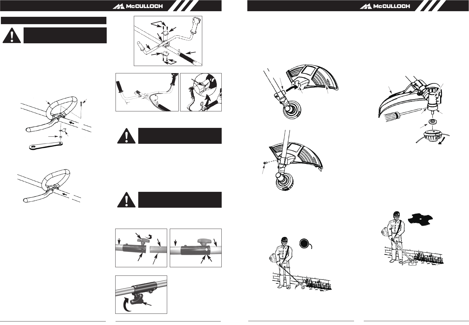
1. Insert bracket into slot on shield.
2. Pivot shield to align holes in shield and bracket.
1. Align hole in the dust cup with the hole in the side of
the gearbox by rotating the dust cup.
2. Insert a small screwdriver into aligned holes. This will
keep the shaft from turning while tightening trimmer
head.
3. While holding the screwdriver in position, thread
trimmer head onto the shaft in the direction shown on
the decal (counterclockwise). Tighten until secure.
2. Secure shield to bracket with bolt.
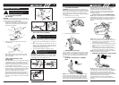
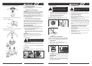
• INSTALLING THE ATTACHMENT
NOTE: To make installing or removing the attachment
easier, place the unit on the ground or on a work bench.
1. Turn the knob (A) counterclockwise to loosen (Fig.
2A).
2. While firmly holding the attachment (B), push it
straight into the Quick-Change coupler (C) until the
release button (D) appears in the primary hole (E) of
the Quick-Change coupler. (Fig. 2B)
3. Turn the knob (A) clockwise to tighten. (Fig. 2C)
All attachments are designed to be used in the primary
hole unless otherwise indicated in the specific attach-
ments operators manual. If the incorrect hole is used, it
could result in injury, or damage to the unit.
WARNING:
To avoid serious personal injury,
shut unit off before removing or installing
attachment.
CAUTION:
The release button must be in the
primary hole and the knob securely tightened
before operating this unit.
6
• ATTACHING THE SHIELD
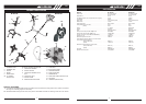
• INSTALLATION OF THE TRIMMER HEAD
• ASSEMBLY INFORMATION - METAL BLADE
• ASSEMBLY INFORMATION - TRIMMER
HEAD
• CONFIGURING YOUR UNIT
Fig. 2A Fig. 2B
Fig. 2C
GB GB
WARNING: The shield must be properly installed. The
shield provides partial protection to the operator and others
from the risk of thrown objects, and is equipped with a line
limiter blade which cuts excess line to the proper length.
The line limiter blade (on underside of shield) is sharp and
can cut you.
You can configure your unit using a cutting head for grass
and light weeds, or a weed blade for cutting grass, weeds,
and brush up to 1 cm in diameter. To assemble your unit,
go to the section for the desired configuration and follow
the instructions.
NOTE: Remove the blade before attaching the trimmer
head. To remove blade, align hole in the dust cup with
the hole in the side of the gearbox by rotating the blade.
Insert a small screwdriver into aligned holes. This will
keep the shaft from turning while loosening the blade nut.
NOTE: If your unit has a plastic cover over the threads on
the threaded shaft, remove the covering to expose the
threads. Before installing the trimmer head, make sure the
dust cup and retaining washer are positioned on the
gearbox.
NOTE: Make sure all parts are properly installed as
shown in the illustration before installing the trimmer head.
NOTE: Remove the trimmer head before installing
the weed blade. To remove the trimmer head, align hole
in the dust cup with the hole in the side of the gearbox by
rotating the dust cup. Insert a small screwdriver into
aligned holes. This will keep the shaft from turning while
loosening the trimmer head. Remove the trimmer head by
turning clockwise. Remove the screwdriver.
See INSTALLATION OF THE CUTTING HEAD for
illustrations. Be sure to store all parts and instructions for
future use.
NOTE: The retaining washer must be positioned with the
raised section facing toward the gearbox.
Remove blade nut by turning clockwise. Remove the
screwdriver. Remove both washers and blade.
See INSTALLATION OF THE METAL BLADE for
illustrations. Be sure to store all parts and instructions
for future use. Never use the trimmer head with the
metal blade installed.
Slot
Shield
Bracket
Bolt
TRIMMER
HEAD
Retaining washer
Dust cup
Gearbox
Aligned holes
Shield
METAL
BLADE
D
A
E
E
D
B
C
C
B
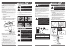
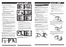
• “P” ATTACHING THE HANDLE
(MT 305 CPS)
1.
2. Install the bolt, securing plate and nut as shown
in the illustration.
3. Make a final adjustment of the handle to a comfor-
table working position. Tighten the nut firmly with
wrench (provided).
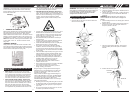
• “BIKE¨ HANDLE INSTALLATION
(MB 305 CBS)
1. To install handle onto unit, you will need the following
components from your user kit: “Bike” handle (A), fix-
ing holder (B), clamp (C) and screws (D). (Fig. 1C)
2.
4. Install wire tie (F) included in the user kit as shown
(Fig. 1E).
ASSEMBLY INSTRUCTIONS
DANGER: To avoid serious injury, the barrier portion of
the handle must be installed as shown to provide a barrier
between operator and the spinning blade.
Wrench
Handle
Bolt
Securing
plate
Nut
WARNING: Please assemble the unit according
to the assembly instructions. Failure to do
so may cause injury to the operator.
(E), and adjust it to a proper position.
Install the fixing holder (B) before the sponge sleeve
3. Install the Bike handle (A) on the fixing holder (B), put
the other clamp (C) over bike-handle, adjut handle to
appropriate position and tighten the other 2 screws
(D). The left handle shall be at least 200mm
horizontally perpendicularly from the shaft tube. The
handle shaft must be mounted on the right side of
direction of arrow head on the handle shaft. (Fig.1D)
Position the loop handle on the shaft. Note that the
handle must be mounted in front of direction arrow
on the shaft. (The distance between both handles
shall be at least 250mm.)
90ß
Fig. 1D Fig. 1E
Fig. 1C
D
B
A
C
C
D
E
F
200mm
(minimum)