


8
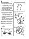
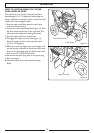
HOW TO ASSEMBLE THE HANDLE
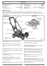
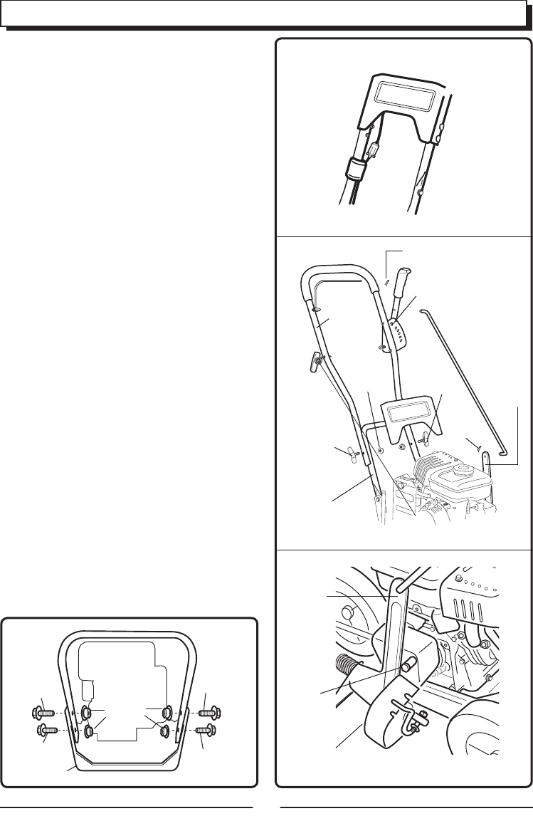
1. Mount the lower handle to the inside of the edger
frame with the (4) M8X16 bolts
, and (4) M8 Nuts
(See Figu
re 3). As you tighten the fasteners, pull back
on the handl
e. The torque for all nuts and bolts in the
handle should be 7.4-11.8
foot-pounds [10-16 Nm].
2. Assemble panel with nuts and bolts provided. Insure
that the
nuts are to the inside. Assemble the top
folding handle with the 2 handle lock levers and
bolts p
rovide. Tighten folding Handles in to position
by tightening locking handles by hand.
3.
4)
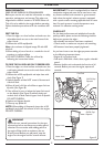
4. Use the (2) cable ties to secure the loose cable
coming f
rom the start lever to the handle. Use (1)
cable tie on the right side of the upper handle and
(1) cable tie on the left side of the l
ower handle.
Ma
ke sure cable goes behind handle panel.
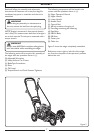
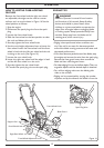
5. Slide one end of the control rod from left to right
th
rough the hole in the clutch lever. Secure with the
cotter pin
. (See Figure 5)
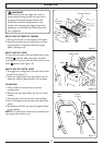
6. Move the clutch lever to the first depth position.
Attach the other end of the cont
rol rod to the quill
suppo
rt arm with the cotter pin. (See Figure 5)
7. Move the clutch lever back to the “N” NEUTRAL
position.
NOTE: If it is difficult to move the clutch lever to the
“N” NEUTRAL position
, loosen the fasteners that hold
the l
ower handle to the edger frame (See Figure 5). Raise
the handle until the clutch l
ever will easily move to the
“N” NEUTRAL position
. Tighten the fasteners.
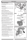
8. When the clutch lever is in the NEUTRAL position,
the quill suppo
rt arm must be close to the screw.
(See Figu
re 6)
ASSEMBLY
Figure 3
Figu
re 4
Figu
re 5
Figu
re 6
M8x16
M8x16
M8x16
M8x16
Edger Frame
M8 Nuts
Edger Engine
Cotter Pin
Neutral
Position
Cont
rol
Rod
Quill
Suppo
rt
Arm
Lower
Handle
Locking
Handles
M8 Nut
Upper
Handle
Cotter
Pin
Quill
Support
Arm
Sc
rew
Locking
Handles
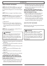
Connect the wires using the plastic connectors fitted.
Secure wires with handle clips provided.
(See Figure