


4
3
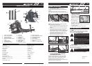
1. THROTTLE TRIGGER
2. THROTTLE ADJUSTER
3. ON/STOP SWITCH
4. TOP ASSIST HANDLE
5. SPARK PLUG WIRE / SPARK
PLUG
6. CHOKE LEVER
7. STARTER HANDLE
8. AIR CLEANER COVER
9. FUEL CAP
10. FUEL TANK
11. PRIMER BULB
12. HARNESS
13. CONTROL HANDLE
14. OPERATING TUBE
15. HOSE CLAMP
16. FLEX TUBE
17. THROTTLE LINKAGE
18. MUFFLER COVER
19. SPARK ARRESTER SCREEN
20. VENTED BACK PAD
21. INTERMEDIATE TUBE
22. 56mm NOZZLE
23. 40mm CONCENTRATOR
NOZZLE
24. THROTTLE LINKAGE CLIPS
GENERAL IDENTIFICATION
SPECIFICATIONS
Engine Type . . . . . . . . . . . . . . . . . . . . . . . . . . . . . . . . . . . . . . . . . . . . . . . . Air-cooled, 2-Cycle
Engine displacement . . . . . . . . . . . . . . . . . . . . . . . . . . . . . . . . . . . . . . . . . 30 cm
3
(1.83 ci)
Engine Speed . . . . . . . . . . . . . . . . . . . . . . . . . . . . . . . . . . . . . . . . . . . . . .>7,800 min
-1
Idle Speed . . . . . . . . . . . . . . . . . . . . . . . . . . . . . . . . . . . . . . . . . . . . . . . . . 3,400-4,400 min
-1
Air Velocity . . . . . . . . . . . . . . . . . . . . . . . . . . . . . . . . . . . . . . . . . . . . . . . . . 467 km/h
Air Output . . . . . . . . . . . . . . . . . . . . . . . . . . . . . . . . . . . . . . . . . . . . . . . . . 13.11 m³/min
Spark Plug Gap . . . . . . . . . . . . . . . . . . . . . . . . . . . . . . . . . . . . . . . . . . . . 0.025 in (0.635 mm)
Fuel Capacity . . . . . . . . . . . . . . . . . . . . . . . . . . . . . . . . . . . . . . . . . . . . . . . 18.5 oz (550 ml)
Dry Weight . . . . . . . . . . . . . . . . . . . . . . . . . . . . . . . . . . . . . . . . . . . . . . . . . 6.4 kg
Sound power level . . . . . . . . . . . . . . . . . . . . . . . . . . . . . . . . . . . . . . . . . . . 102 dB(A)
Sound pressure level at ear . . . . . . . . . . . . . . . . . . . . . . . . . . . . . . . . . . . . 94 dB(A)
Guarantee sound power level . . . . . . . . . . . . . . . . . . . . . . . . . . . . . . . . . . 104 dB(A)
Vibration . . . . . . . . . . . . . . . . . . . . . . . . . . . . . . . . . . . . . . . . . . . . . . . . . . . 3.17m/s
2
EN ISO 22868 : 2005.
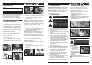
• ATTACH FLEX TUBE
• ATTACH OPERATING TUBE
NOTE: keep the throttle cable as straight as possible
when connecting the blower tubes.
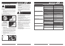
• ATTACH INTERMEDIATE TUBE AND
CONCENRATOR NOZZLE
• ADJUST BACK PACK AND HARNESS AND
CONTROL HANDLE
1. Place blower on your
back by slipping arms
through the shoulder
straps as if you were
putting on a jacket (Fig.
8).
2. Once adjustments
have been made, to
the straps for user
comfort, remove the
blower from your back and place on level ground in
an upright position.
3. Adjust backpack harness and control handle.
• FUEL
Use regular grade unleaded petrol mixed with 40:1
custom 2-cycle engine oil for best results. Use mixing
ratios in Section FUEL MIXING TABLE.
• MIXING FUEL
Add oil to an approved fuel container followed by the
petrol to allow incoming petrol to mix with oil. Shake
container to ensure thorough mix.
• FUEL AND LUBRICATION SYMBOLS
Put the hose clamp(C) on the flex tube(B) before
connecting the flex tube(B) and the fan’s outlet tube(A)
together.
Connect the flex tube (B) to the fan’s outlet tube (A)
(Fig. 1) with a hose clamp (C) (Fig.2) and tighten securely
(Fig. 2).
Connect the intermediate tube (H) and concentrator
nozzle (I) or 56mm nozzle (J) (you can only use one
nozzle at a time). Push the tubes together and turn
clockwise until they lock together (Fig. 7). Use
concentrator nozzle when you need more airflow in tight
places: flower beds, under decks, etc.
1. Place the unit on flat surface during assembly. Insure
screw mechanism of clamp is positioned away from
operator.
2. Put the hose clamp (C) on the flex tube(B) and the
operating tube before connecting them together.
3. Turn the throttle linkage mark (D) so it aligns with the
throttle handle (F) (Fig.3). Insert the operating tube
(E) into the flex tube (B) (Fig. 3) and then tighten
securely with a hose clamp (G) (Fig. 4).
4. Attach throttle linkage clips to both ends of the flex
tube to secure the throttle cable. (Fig. 6)
ASSEMBLY INSTRUCTIONS
Fig. 8
WARNING: Never use straight petrol in your
unit. This will cause permanent engine damage and
void the manufacturer’s warranty for that product.
Never use a fuel mixture that has been stored for over
90 days.
WARNING: If 2-cycle lubricant other than
Custom Lubricant is to be used, it must be a premi-
um grade oil for 2-cycle air cooled engines mixed at
a 40:1 ratio. Do not use any 2-cycle oil product with
a recommended mixing ratio of 100:1. If insufficient
lubrication is the cause of engine damage, it voids
the manufacturer’s engine warranty.
WARNING: Lack of lubrication voids engine
warranty. Petrol and oil must be mixed at 40:1.
Petrol and oil
mix 40:1
FUEL AND LUBRICATION
Fig. 1
A
Fig. 2
B
C
Fig. 3
B
Fig. 4
180˚
D
F
E
G
Fig. 5
Fig. 6
THROTTLE LINKAGE
CLIPS
THROTTLE LINKAGE CLIPS
Fig. 7
B
D
H
I
J
40mm
56mm
GB
GB