


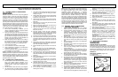
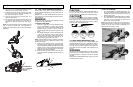
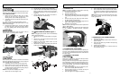
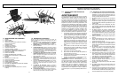

THE PUSH (PINCH-KICKBACK) AND PULL
REACTIONS (Figure 2-4B)
A = Pull
B = Solid objects
C = Push
KICKBACK may occur when the NOSE or TIP of the guide
bar touches an object, or when wood closes in and pinch-
es the saw chain in the cut.
Tip contact in some cases may cause a lightning-fast
reverse reaction, kicking the guide bar up and back toward
the operator.
PINCHING the saw chain along the BOTTOM of the guide
bar may PULL the saw forward away from the operator.
PINCHING the saw chain along the TOP of the guide bar
may PUSH the guide bar rapidly back toward the operator.
Any of these reactions may cause you to lose control of the
saw, which could result in serious personal injury.
2-5. KICKBACK SAFETY LABELS
Your McCulloch Chain Saw is provided with a safety label
located on the chain brake lever. This label, along with the
safety instructions on these pages, should be carefully read
before attempting to operate this unit.
HOW TO READ SYMBOLS AND COLORS:
WARNING
Used to warn that an unsafe procedure should not be per-
formed.
RECOMMENDED
Recommended cutting procedures.
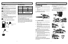
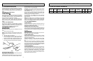
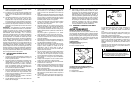
WARNING (Figure 2-5A)
1. Worst-case computed kickback angle.
2. Beware of kickback.
3. Do not attempt to hold saw with one hand.
4. Avoid bar nose contact.
RECOMMENDED
5. Hold saw properly with both hands.
GREEN
RED
2-4B
A
C
B
B
6 7
The engine exhaust from this product contains chemi-
cals known to the State of California to cause cancer,
birth defects, or other reproductive harm.
WARNING
2-5A
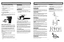
2-6. INTERNATIONAL SYMBOLS
Wear head, eye and hearing protection.
Wear gloves to protect your hands.
Wear safety boots to protect against electric shock.
Read User Manual.
Use of these personal safety items is
highly recommended to reduce the risk
of accidental injur
y.
2 - SAFETY PRECAUTIONS 3 - ASSEMBLY INSTRUCTIONS
3-1. INTRODUCTION
This unit is designed f
or occasional homeowner use and
should not be used for commercial purposes or subjected
to heavy continuous use.
Your new chain saw can be used for a variety of projects
such as cutting firewood, making fence posts, felling small
trees, limbing, pruning at ground level, and light carpentry.
Cut only wood or wood products with your saw.
3-2. ASSEMBLY REQUIREMENTS
Your new chain saw will require adjustment of chain, filling
the fuel tank with correct fuel mixture and filling the oil tank
with lubricating oil before the unit is ready for operation.
WARNING
DO NOT start saw engine until unit is properly prepared.
Read the entire user manual before attempting to operate
your unit. Pay particular attention to all safety precautions.
Your user manual is both a reference guide and handbook
provided to furnish you with general information to assem-
ble, operate and maintain your saw.
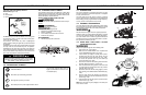
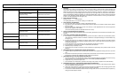
3-3. GUIDE BAR / SAW CHAIN / CLUTCH
COVER INSTALLATION
WARNING
Always wear protective gloves when handling chain.
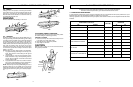
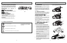
1. Place power unit on flat surface.
2. Make sure the CHAIN BRAKE
®
lever is pulled back
into the DISENGAGED position. (Fig. 3-3A)
3. Loosen button (C) slightly by turning knob counter-
clockwise and then turn the chain tension ring (B)
counter-clockwise to relief chain tension. (Fig. 3-3B)
4. To remove the sprocket cover (A), turn button (B)
counter-clockwise. (Fig. 3-3B)
5.
Remove saw chain from around the guide bar and the
sproc
k
et.
Slide the guide bar, from the unit.
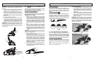
6. Place the slotted end of the guide bar over the bar bolt
(D).
Slide guide bar behind clutch drum (E) until the
guide bar stops. (Fig. 3-3C)
7.
Spread the chain out with the cutting edges (F) of the
chain pointing in the DIRECTION OF R
OTATION (Fig.
3-3D).
8. Slip the chain around the sprocket (G) behind the
clutch (H).
Mak
e sure the links fit between the sprock-
et teeth. (Fig. 3-3E)
9. Guide the drive links into the groove (I) and around the
end of the bar. (Fig. 3-3E)
NOTE: The saw chain may droop slightly on the lower part
of bar
.
This is normal.
3-3A
3-3B
A
B
C
3-3C
3-3D
3-3E
E
D
E
H
G
I