


6
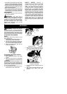
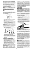
S Tipcontactinsomecasesmaycausealight-
ning fast reverse REACTION, kicking the
guide bar up and back toward the operator .
S Pinchingthesawchainalongthetopofthe
guide bar may push the guide bar rapidly
back toward the operator.
S Eitherofthesereactionsmaycauseyouto
lose control of the saw which could result
in serious injury. Do not rely exclusively
uponthesafetydevicesbuiltintoyoursaw.
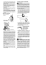
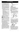
CHAIN BRAKE
S Chainbrake, designedtostop the chainin
the e vent of kickback.
WARNING: Your chain saw i s
equippedwithachain brakethatisdesigned
to stop the chain immediately if you get a
kickback. The chain brake reduces the risk
ofaccidents, butonly youcan preventthem.
DO NOT ASSUME THAT THE CHAIN
BRAKE WILL PROTECT YOU IN THE
EVENT OF A KICKBACK.
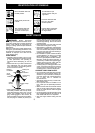
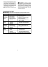
SAFETY NOTICE: Exposure to
vibrationsthroughprolongeduseofgasoline
powered hand tools could cause blood
vessel or nerve damage in the fingers,
hands, and joints of people pr one to
circulation disorders or abnormal swellings.
Prolonged use in cold weather has been
linked to blood vessel damage in otherwise
healthy people. If symptoms occur such as
numbness, pain, loss of strength, change in
skin color or texture, or loss of feeling in the
fingers,hands,or joints,discontinue the use
of this tool and seek medical attention. An
anti-v ibrationsystemdoesnotguaranteethe
avoidance of these problems. Users who
operate power tools on a continual and
regular basis must monitor closely their
physical condition and the condition of this
tool.
ASSEMBLY
WARNING: Recheck each assem-
bly step if the saw is received assembled.
Protective gloves (not provided) should be
worn during assembly . Always wear gloves
whenhandling the chain. Thechainissharp
and can cut you even when it is not moving!
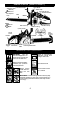
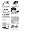
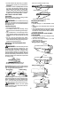
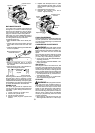
ATTACHING THE BUMPER
SPIKE
The bumper spike may be used as a pivot
when making a cut.
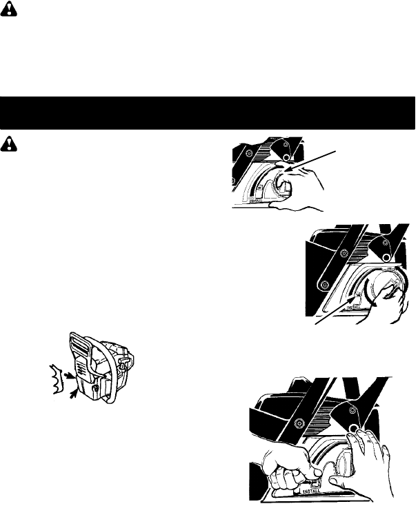
1. Liftadjustmentknob handle and turncoun-
terclockwise to loosen chain brake.
2. Align arrows by pressing tensioning le-
ver down to install position (see illustra-
tion). Remove chain brake from saw.
3. Attach the bumper spike with the two
screws as illustrated.
ATTACHING THE BAR & CHAIN (If
not already attached)
1. MoveON/STOPswitchtotheSTOP
position.
2. Make sure chain brake is disengaged
(seeCHAINBRAKEintheOPERATION
section).
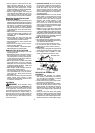
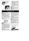
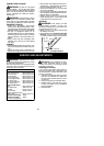
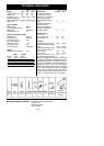
IMPORTANT: Before proceeding to next
step,ensureunitisonaflatsurfaceandinan
upright position as shown in illustration be-
low. Chainwill nottighten properly ifthe unit
is not in an upright position.
3. Liftadjustmentknob handle and turncoun-
terclockwise to loosen chain brake.
Adjustment
Knob
Handle
Tensioning Lever
LOOSEN
4. Align arrows by pressing tensioning le-
ver down to install position (see illustra-
tion). Remove chain brake from saw.
TENSIONING LEVER IN
INSTALL POS ITION
5. Remove the plastic shipping spacer (if
present).
6. Slide guide bar behind clutch drum until
guide bar stops against clutch drum
spro cke t .