5
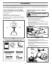
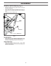
Fig. 4
TILLING WIDTH
• Tilling width may be adjusted to better handle your
tilling con di tions (See “TINE ARRANGEMENT” in the
Service and Adjustments section of this manual.)
TINE OPERATION
• Check tine operation before first use. (See “TINE
OPERATION CHECK” in the Service and Adjustments
section of this manual.)
TO INSTALL DEPTH STAKE (See Fig. 4)
• Remove screw(s) securing depth stake to skid and
discard the screw(s).
• Slide depth stake down into transport arm track, lin-
ing up a hole in the depth stake with hole in transport
arm.
• Install clevis pin and hairpin clip.
ASSEMBLY
DEPTH
STAKE
HAIRPIN CLIP
CLEVIS PIN


